4
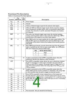
Functional Pin Description
Table 4. Functional Pin Descriptions
Pin
Pin
Symbol 2000/2016 2020
Description
VDD
VSS
16
8
20
10
2
Power Supply
Ground
CLK
2
CLK is a Schmitt-trigger input for the external clock signal.
CHA
CHB
7
6
9
8
CHA and CHB are Schmitt-trigger inputs which accept the outputs
from a quadrature encoded source, such as incremental optical shaft
encoder. Two channels, A and B, nominally 90 degrees out of phase,
are required.
RST
OE
5
4
7
4
This active low Schmitt-trigger input clears the internal position
counter and the position latch. It also resets the inhibit logic. RST is
asynchronous with respect to any other input signals.
This CMOS active low input enables the tri-state output buffers. The
OE and SEL inputs are sampled by the internal inhibit logic on the
falling edge of the clock to control the loading of the internal position
data latch.
SEL
3
3
This CMOS input directly controls which data byte from the position
latch is enabled into the 8-bit tri-state output buffer. As in OE above,
SEL also controls the internal inhibit logic.
SEL
BYTE SELECTED
0
1
High
Low
CNTDCDR
U/D
16
5
A pulse is presented on this LSTTL-compatible output when the
quadrature decoder has detected a state transition.
This LSTTL-compatible output allows the user to determine whether
the IC is counting up or down and is intended to be used with the
CNTDCDR and CNTCAS outputs. The proper signal U (high level) or D
(low level) will be present before the rising edge of the CNTDCDR and
CNTCAS outputs.
CNTCAS
15
A pulse is presented on this LSTTL-compatible output when the
HCTL-2020 internal counter overflows or underflows. The rising edge
on this waveform may be used to trigger an external counter.
D0
D1
D2
D3
D4
D5
D6
D7
NC
1
1
These LSTTL-compatible tri-state outputs form an 8-bit output port
through which the contents of the 12/16-bit position latch may be read in
2 sequential bytes. The high byte, containing bits 8-15, is read first (on the
HCTL-2000, the most significant 4 bits of this byte are set to 0 internally).
The lower byte, bits 0-7, is read second.
15
14
13
12
11
10
9
19
18
17
14
13
12
11
6
Not connected - this pin should be left floating.

 AGILENT [ AGILENT TECHNOLOGIES, LTD. ]