VAR1
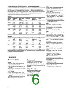
Capacitance Calculation Accuracy (Supplemental Data)
Accuracy is derived from the current range, voltage range, capacitance measurement and
leakage current measurement integration times, and the guard capacitance of cabling
and step voltage. The information in the chart below is based on the following condi-
tions: Voltage Range 20 Vꢂ Voltage Step: 100 mVꢂ Guard Capacitance: 100 pFꢂ Equivalent
parallel resistance of DUT: 1 ꢁ 1015 Ω. The ratio of integration times for capacitance
measurement and leakage current measurement is 1:1.
Primary sweep controls the staircase (dc
or pulsed) voltage or current sweep.
Maximum number of steps: 1001 for one
VAR1 sweep.
Sweep type: linear or logarithmic
Sweep direction: Single or double sweep
Hold time: Initial wait time or wait time
after VAR2 is set: 0 to 655.35 s with 10
ms resolution
Delay time: Wait time from VAR1 step to
the start of the measurement: 0 to 65.535
s with 100 μs resolution
HRSMU
Current
Range
10 pA/
100 pA
Integration
Time
0.5 sec
1 sec
2 sec
0.1 sec
0.5 sec
2 sec
Max. Meas. Resolution
Value
Accuracy
Reading %
4.2
Offset
100 pF/1 pF 5 fF
70 fF
+0 fF
2 pF/20 pF
10 fF
4.3
VAR2
76 pF/760 pF 20 fF
4.3
130 fF
160 fF
280 fF
740 fF
200 fF
440 fF
1.4 pF
6.2 pF
Subordinate linear staircase or linear
pulsed sweep. After primary sweep
is completed, the VAR2 unit output is
incremented.
1 nA
700 pF
4.5 nF
18 nF
7 nF
45 nF
180 nF
+40 nF
10 fF
40 fF
200 fF
10 fF
40 fF
200 fF
1 pF
0.84
0.85
0.+3
10 nA
0.1 sec
0.5 sec
2 sec
0.84
Maximum number of steps: 128
VAR1'
0.85
0.+3
Staircase or pulse sweep synchronized with
the VAR1 sweep. Sweep is made with a
user specified ratio and offset value. VAR1'
output is calculated as VAR1' = a ꢁ VAR1
% b, where “a” is the user specified ratio
and “b” is the user specified offset value.
10 sec
1.3
MPSMU
Current
Integration
Time
0.1 sec
0.5 sec
2 sec
Max. Meas. Resolution
Value
Accuracy
Reading %
0.+1
Offset
1 nA
700 pF
4.5 nF
18 nF
7 nF
10 fF
40 fF
200 fF
10 fF
40 fF
200 fF
1 pF
170 fF
340 fF
1 pF
180 fF
480 fF
1.6 pF
7.6 pF
CONSTANT
0.+4
A source unit can be set as a constant
voltage or current source depending on
the unit.
1.0
10 nA
0.1 sec
0.5 sec
2 sec
0.+1
45 nF
180 nF
+40 nF
0.+4
PULSE
1.0
1.6
One of the SMUs can be set as a pulse
source.
10 sec
Current compliance must be smaller than the current range. The capacitance of the DUT and measurement path must
be smaller than the maximum measurement value.
Pulse width: 0.5 ms to 100 ms, 100 μs
resolution.
Pulse period: 5 ms to 1 s (pulse
width % 4 ms), 100 μs resolution.
SMU pulse setting accuracy
(supplemental information, at fixed
range measurement except multichannel
measurement):
Functions
Measurement Setup
Measurement
Width: 0.5ꢀ % 50 μs
The 4155C and 4156C can perform dc
or pulsed force/measure, and stress
force. For dc, voltage/current sweep and
sampling (time domain) measurements are
available.
Period: 0.5ꢀ % 100 μs
Setting
Trigger output delay for pulsed measure-
ment: 0 - 32.7 ms with
• Fill-in-the-blanks using front-panel or
full-size external keyboard
• Load settings from floppy disk or via the
LAN port
100 μs resolution (< pulse width).
• Program using internal Instrument BASIC
or via GPIB
Voltage/Current Sweep
Measurement Characteristics
Each SMU and VSU can sweep
using VAR1 (primary sweep),
VAR2 (subordinate sweep), or
VAR1 (synchronous sweep).
• HELP Function
• Library: Default measure setup, Vce-Ic,
Vds-Id, Vgs-Id, and Vf-If are predefined
softkeys
• User-defined measurement setup library
• Auto file load function on power-up
6

 AGILENT [ AGILENT TECHNOLOGIES, LTD. ]