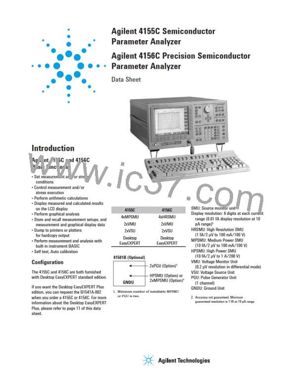
Burst count range: 1 – 65535
Pulse parameter accuracy:
Period: (2ꢀ %2 ns)
PGU (Pulse Generator Unit)
Specifications
MPSMU Specifications
Same as 4155C MPSMU.
Width: (3ꢀ %2 ns)
Modes: Pulse or constant
Amplitude: 0 Vp-p to 40 Vp-p
Window: -40.0 V to %40.0 V
Maximum current:
Delay: (2ꢀ %40 ns)
GNDU (Ground Unit)
Specifications
Output Voltage: 0 V 100 μV
Maximum sink current: 1.6 A
Output terminal/connection:
Single triaxial connector,
Kelvin (remote sensing)
Transition time: (5ꢀ %10 ns)
Trigger output:
Level: TTL
100 mA
Timing: Same timing and width as
PGU1 pulse output
200 mA (pulse width: ≤1 ms, average
current 100 mA)
PGU Supplemental Information
Overshoot: ≤ 5ꢀ of amplitude 10 mV (50
Ω output impedance to 50 Ω load)
Pulse width jitter: 0.2ꢀ % 100 ps
Pulse period jitter: 0.2ꢀ % 100 ps
Maximum slew rate: 100 V/μs (50 Ω
output impedance to 50 Ω load)
Noise: 0.2ꢀ of range (@ DC output)
Pulse width: 1.0 μs to +.++ s
Minimum resolution: 100 ns
Pulse period: 2.0 μs to 10.0 s
Minimum resolution: 100 ns
Delay: 0 s to 10 s
GNDU Supplemental Information
Load Capacitance: ≤1 μF
Cable resistance:
Force ≤1 Ω
Sense ≤10 Ω
Minimum resolution: 100 ns
Transition time: 100 ns to 10 ms
Minimum resolution: 1 ns
Output impedance: 50 Ω or low
impedance (≤1 Ω)
HRSMU, MPSMU, HPSMU
Supplemental Information
Maximum capacitive load: 1000 pF
Maximum guard capacitance: +00 pF
Maximum shield capacitance: 5000 pF
Maximum guard offset voltage: 1 mV
Noise characteristics
Pulse/DC Output Voltage and Accuracy (PGU)
Set
Parameter
Voltage Range
Resolution
Accuracy1
Base
20 V
40 V
20 V
40 V
4 mV
8 mV
4 mV
8 mV
(1ꢀ of Base %50 mV %1ꢀ of Pulse)
(1ꢀ of Base %50 mV %1ꢀ of Pulse)
(3ꢀ of Base %50 mV)
(typical, Filter: ON):
Pulse
Voltage source noise:
(3ꢀ of Base %50 mV)
0.01ꢀ of V range (rms)
Note: DC output is performed by the Base Parameter.
Current source noise:
1 Accuracy is specified at leading edge - trailing edge = 1 μs
0.1ꢀ of I range (rms)
Voltage monitor noise:
0.02ꢀ of V range (p-p)
Pulse Range and Pulse Parameter (PGU)
Current monitor noise: 0.2ꢀ of I
Output overshoot (typical, Filter: ON):
Voltage source: 0.03ꢀ of V range
Current source: 1ꢀ of I range
Range switching transient noise (typical,
Filter: ON):
Range
Period
Width
Delay
Set Resolution
1
2
3
4
5
6
2 μs -100 μs
100 μs - 1000 μs
1 ms - 10 ms
10 ms - 100 ms
100 ms - 1000 ms
1 s - 10 s
1 μs - ++.+ μs
1 μs - +++ μs
.01 ms - +.++ ms
0.1 ms - ++.+ ms
1 ms - +++ ms
0.01 s - +.++ s
0 - 100 μs
0 - 1000 μs
0 - 10 ms
0 - 100 ms
0 - 1000 ms
0 - 10 s
0.1 μs
1 μs
10 μs
100 μs
1 ms
Voltage ranging: 250 mV
10 ms
Current ranging: 10 mV
Note: Pulse width is defined when leading time is equal to trailing time.
PGU2 must be set in the same range as PGU1
Maximum slew rate: 0.2 V/μs
Leading/Trailing Edge Times (PGU)
Range
Set Resolution
1 ns
Accuracy
100 ns - 1000 ns
0.5 μs - 10 μs
5.0 μs - 100 μs
50 μs - 1000 μs
0.5 ms - 10 ms
Restrictions:
(5ꢀ % 10 ns)
(5ꢀ % 10 ns)
(5ꢀ % 10 ns)
(5ꢀ % 10 ns)
(5ꢀ % 10 ns)
10 ns
100 ns
1 μs
10 μs
Pulse width < Pulse Period, Delay time < Pulse period, Leading time < Pulse width ꢁ 0.8
Trailing time < (Pulse period - Pulse width) ꢁ 0.8
Period, width, and delay of PGU1 and PGU2 must be in the same range. Leading time and
trailing time for a PGU must be in the same range.
5

 AGILENT [ AGILENT TECHNOLOGIES, LTD. ]