Ambassador T8100A, T8102, and T8105
H.100/H.110 Interfaces and Time-Slot Interchangers
Advance Data Sheet
November 1999
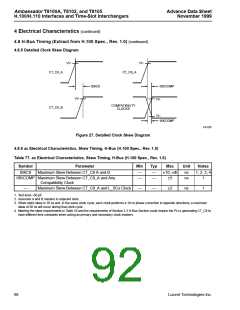
4 Electrical Characteristics (continued)
4.6 dc Electrical Characteristics, H-Bus (ECTF H.100 Spec., Rev. 1.0)
4.6.1 Electrical Drive Specifications—CT_C8 and /CT_FRAME
Table 74. Electrical Drive Specifications—CT_C8 and /CT_FRAME
VDD = 3.3 V and VSS = 0.0 V unless otherwise specified.
Parameter
Symbol
Condition
Min
Max
Unit
Output High Voltage
VOH
VOL
Vt+
Vt–
IOUT = –24 mA
2.4
–0.25
1.2
3.3
0.4
2.0
1.6
—
V
V
Output Low Voltage
IOUT = 24 mA
Positive-going Threshold
Negative-going Threshold
Hysteresis (Vt+ – Vt–)
Input Pin Capacitance
—
—
—
—
V
0.6
V
VHYS
CIN
0.4
V
—
10
pF
PCI-compliant data line I/O cells are used for the CT bus data lines. (See PCI Specification, Rev. 2.1, Chapter 4.)
/C16, /C4, C2, SCLK, SCLKX2, and /FR_COMP all use the same driver/receiver pairs as those specified for the
CT_C8 and /CT_FRAME signals, though this is not explicitly stated as a part of the H.100 Specification.
4.7 dc Electrical Characteristics, All Other Pins
Table 75. dc Electrical Characteristics, All Other Pins
VDD = 3.3 V and VSS = 0.0 V unless otherwise specified.
Description
Supply Current
Symbol
Condition
Min
Typ
Max
Unit
IDD
VDD
VIH
VIL
—
—
3.0
2.0
—
175*
—
—
—
—
—
—
—
—
—
—
—
275*
3.6
—
mA
V
Supply Voltage
—
Input High Voltage
—
V
Input Low Voltage
—
0.8
1
V
Input Current
II
—
—
µA
pF
pF
µA
V
Input Capacitance (input only)
Input Capacitance (I/O pins)
Leakage Current (3-state)
Input Clamp Voltage
Output High Voltage
Output Low Voltage
Output Short-circuit Current
CI
—
—
5
CIO
ILEAK
VC
—
—
10
—
—
10
—
—
–1.0
—
VOH
VOL
IOS
—
—
2.4
—
V
0.4
100
V
VOH tied to GND
—
mA
* Circuit simulation indicates a typical current of 175 mA and a worst-case current of 275 mA. This parameter is not tested in production.
84
Lucent Technologies Inc.

 AGERE [ AGERE SYSTEMS ]