Ambassador T8100A, T8102, and T8105
H.100/H.110 Interfaces and Time-Slot Interchangers
Advance Data Sheet
November 1999
4 Electrical Characteristics (continued)
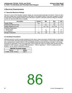
4.3 Crystal Information
Table 72. Crystal Specifications
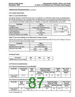
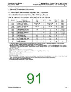
The devices require a 16.384 MHz clock source. To supply this, a 16.384 MHz crystal can be connected between
the XTALIN and XTALOUT pins. External 18 pF, 5% capacitors must be connected from XTALIN and XTALOUT to
VSS. Crystal specifications are shown below. The ±32 ppm tolerance is the suggested value if the oscillator is used
as the clocking source while mastering the bus. Otherwise, a crystal with a lesser tolerance can be used.
Parameter
Value
16.384 MHz
XTALOUT
Frequency
18 pF
18 pF
T8100A
T8102
T8105
Oscillation Mode
Fundamental, Parallel Resonant
40 Ω maximum
14 pF
1 MΩ
Effective Series Resistance
Load Capacitance
XTALIN
16.384 MHZ
VSS
Shunt Capacitance
7 pF maximum
32 ppm
5-6390(F)
Frequency Tolerance and Stability
Table 73. Use of an Oscillator as an Alternative to Using a Crystal
XTALIN can be driven by a CMOS signal instead of a crystal. XTALIN and XTALOUT are not 5 V tolerant. The oscil-
lator must meet the requirements shown below.
Parameter
Value
Frequency
16.384 MHz
Maximum Rise or Fall Time
Minimum Pulse Width
10 ns, 10% to 90% VDD
Low
20 ns
High
20 ns
4.4 Reset Pulse
Parameter
Min
Max
Unit
ns
RESET Minimum Pulse Width
61
—
4.5 Thermal Considerations
4.5.1 Thermal Considerations for the 208 SQFP
Parameter
Construction
Details
Body
Size
(mm sq.)
Thermal Numbers
Theta-JA (°C/W)
Paddle
Size
(mil sq.)
Max. Power
(Natural
Convection)
(Watts)
Natural
200 fpm 500 fpm
Convection
4-Layer JEDEC
Test Board
Cu L.F.
20
26.5
23 21
433
2.1
4.5.2 Thermal Considerations for the 217 PBGA
Parameter
Body
Size
(mm sq.)
Array
Details
Ball
Pitch
(mm)
Number
of
Layers
Thermal Numbers
Theta-JA (°C/W)
Max. Power
(Natural
Convection)
(Watts)
Natural
200 fpm 500 fpm
Convection
4-Layer JEDEC
Test Board
23
Peripheral
+ T.A.
1.27
2
32.5
29 27.5
1.7
Lucent Technologies Inc.
83

 AGERE [ AGERE SYSTEMS ]