Ambassador T8100A, T8102, and T8105
H.100/H.110 Interfaces and Time-Slot Interchangers
Advance Data Sheet
November 1999
3 Using the TSI Devices (continued)
3.4 Using the LAR, AMR, and IDR for Connections (continued)
3.4.3 Programming Examples (continued)
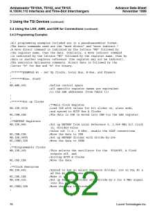
;
;**Optional: Test CAM Busy bit**
TEST:
MD,ACC,MCR
AND,01h
JNZ TEST
;Move MCR contents into (host’s) accumulator (for example)
;Logical AND, i.e., mask off all but LSB of the MCR register
;If the LSB is zero (not busy), continue, else jump back and
;retest
;
CONTINUE:
;
;******Set up the “to” connection
;
MD,AMR,0B0h
;Point to the Time-Slot holding register
MI,IDR,1Dh
MD,AMR,0B1h
;This is the Time-Slot value (29) for the Local address
;Point to the upper bits of the connection
MI,IDR,100_00011b
:Set up a read from data memory to Local pins,
;
;
disable pattern mode, minimum delay, and set
stream number equal to 00011b (3).
MD,AMR,0B2h
MI,IDR,31h
;
;Point to tag field
;Use location 49 of the associated Data RAM to store the data
MD,AMR,0B3h;
MI,IDR,00h;
MD,AMR,0E3h
MI,IDR,0E3h
;
;Write to next free location in the Local CAM
;The command is executed with the indirect to IDR
;**CAM Busy bit can be tested here**
;
;
;*******END OF EXAMPLE #3
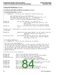
3.4.4 Miscellaneous Commands
These commands (i.e., 0x70, 0xF8, all reset commands in the AMR register) require two writes: first the value is
written to the AMR register; then the same value is written to the IDR register. After writing to the IDR register, the
command will be executed.
Lucent Technologies Inc.
81

 AGERE [ AGERE SYSTEMS ]