Ambassador T8100A, T8102, and T8105
H.100/H.110 Interfaces and Time-Slot Interchangers
Advance Data Sheet
November 1999
3 Using the TSI Devices (continued)
3.4 Using the LAR, AMR, and IDR for Connections (continued)
3.4.3 Programming Examples (continued)
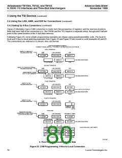
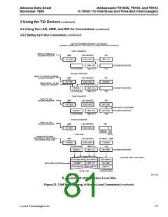
;*******EXAMPLE #2 - Setting up Local Connections (T8100A, T8105 only)
;
;
Use 8 Mbits/s rate set up from Example #1...
;
;
;
Send data FROM Stream/Time Slot 14, 7 TO Stream/Time Slot 3, 29.
To transfer data the local input 14, 7 to the local
output 3, 29 the following programming steps are required.
;
MD,LAR,1Dh
MD,AMR,43h
;Set up lower address, i.e., Time Slot 29
;
Set up upper address bits (Stream 3), and
point to the
;
the Time Slot field of the connection memory
MI,IDR,07h
;
;Put a “7” in the Time Slot field of connection location
3,29
;Syntactically, “MI,IDR,data” is a special case since IDR is not the final recipient
of the data
;
MD,AMR,53h
;Maintain the same upper address, but get ready to load the
;
remaining connection info (upper bits +
control)
MI,IDR,0001_1110b
;This decodes as follows: XCS bit low, pattern mode off
;
(not set), frame bit low, time slot enabled,
and stream = 1110b (14)
;
;*******END OF EXAMPLE #2
;*******EXAMPLE #3 - Setting up H-Bus Connections, No Subrate
;
; Use rate set up from Example #1...
; Send data from Stream 14/Time Slot 7 of the H.100 bus to Stream 3/Time Slot 29
; on the Local side. The data is coming in at 4 Mbits/s from E-CAM, and is sent
; out at 8 Mbits/s to through L-CAM. We’re using Data Memory location 49 to hold
; the actual data. LAR is not used for the CAM connection setups; it is used for
; reading specific CAM locations or writing and reading the associated Data
; Memory Locations.
;
;******Set up the “from” connection
;
MD,AMR,0B0h
;Point to the Time-Slot holding register
MI,IDR,07h
MD,AMR,0B1h
MI,IDR,000_01110b
;This is the Time-Slot value (7) for the H-Bus address
;Point to the upper bits of the connection
:Set up a write into data memory from ECTF bus,
;
;
disable pattern mode, minimum delay,
and set stream number equal to 01110b (14).
MD,AMR,0B2h
MI,IDR,31h
MD,AMR,0B3h
MI,IDR,00h
;
;Point to tag field
;Use location 49 of the associated Data RAM to store the data
;Point to the subrate control and TAG MSB field;
;MSB of location 49 is 0;
MD,AMR,0E0h
MI,IDR,0E0h
;Write to next free location in the Even CAM
;The command is executed with the indirect to IDR which
;uses the same command value as in the AMR.
80
Lucent Technologies Inc.

 AGERE [ AGERE SYSTEMS ]