AD5940
Data Sheet
Timer Command
the end of execution. These interrupts are cleared by writing to
the corresponding bits in the INTCCLR register. The current
value of the counter can be read by the host controller at any
time through the SEQTIMEOUT register.
There are two timer commands in the sequencer, with a
separate hardware counter for each.
The wait command introduces wait states in the sequencer
execution. After the programmed counter reaches 0, the
execution is resumed by reading the next command from
command memory.
The timeout counter is not reset when the sequencer execution
is stopped as a result of a sequencer write command. However,
it is reset if the host controller writes a 0 to the SEQEN bit in the
SEQCON register. This reset applies to situations when the host
must abort the sequence.
The timeout command starts a counter that operates independently
of the sequencer flow. When the timer elapses, one of two
interrupts is generated: a sequence timeout error interrupt,
INTSEL17, or a sequence timeout finished interrupts, INTSEL16.
Both interrupts are configured in the INTCSELx registers. The
sequence timeout finished interrupt is asserted at the end of the
timeout period. The sequence timeout error interrupt is asserted if,
at the end of the timeout period, the sequencer does not reach
The time unit for both timer commands is one ACLK period.
For a clock frequency of 16 MHz, the timer resolution is 62.5 ns,
and the maximum timeout is 67.1 sec. These values are true
even if the SEQWRTMR bits in the SEQCON register are
nonzero.
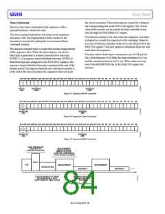
B31 B30 B29 B28 B27 B26 B25 B24 B23 B22 B21 B20 B19 B18 B17 B16 B15 B14 B13 B12 B11 B10 B9 B8 B7 B6 B5 B4 B3 B2 B1 B0
1
BIT[31]
CMD
BITS[30:24]
ADDR
BITS[23:0]
DATA
Figure 35. Sequencer Write Command
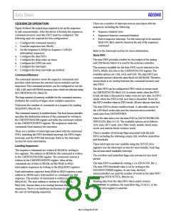
B31 B30 B29 B28 B27 B26 B25 B24 B23 B22 B21 B20 B19 B18 B17 B16 B15 B14 B13 B12 B11 B10 B9 B8 B7 B6 B5 B4 B3 B2 B1 B0
0
1
BITS[31:30]
CMD
BITS[29:0]
TIME
Figure 36. Sequencer Timer Command
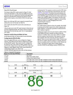
B31 B30 B29 B28 B27 B26 B25 B24 B23 B22 B21 B20 B19 B18 B17 B16 B15 B14 B13 B12 B11 B10 B9 B8 B7 B6 B5 B4 B3 B2 B1 B0
0
0
BITS[31:30]
CMD
BITS[29:0]
TIME
Figure 37. Sequencer Wait Command
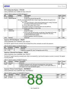
LOAD TRIM VALUES
FROM OTP TO
SHADOW REGISTERS
RUN SEQUENCE
ENABLE/DISABLE
ANALOG BLOCKS,
START ADC CONVERSION,
STORE RESULTS IN SRAM
BOOT
POR
MEASUREMENT
MEASUREMENT
INITIALIZATION
HIBERNATE
HIBERNATE
• • •
LOAD SEQUENCES TO SRAM,
SETUP SEQUENCE, FIFO,
SLEEP WAKE-UP TIMER, GPIOS.
HIBERNATE MODE WITH
SRAM CONTENTS
RETAINED
Figure 38. Run Sequence
Rev. 0 | Page 84 of 130

 ADI [ ADI ]