AD5940
Data Sheet
POWER MODES
There are four main power modes for the AD5940: active high
power mode (>80 kHz), active normal mode (<80 kHz),
hibernate mode, and shutdown mode.
the leakage from the ADC is reduced, which subsequently
reduces the current consumption in hibernate mode.
Optionally, the low power DAC, reference, and amplifiers can
remain active to maintain the bias of an external sensor.
However, current consumption increases.
ACTIVE HIGH POWER MODE (>80 kHz)
Active high power mode (>80 kHz) is recommended when
generating or measuring high bandwidth signals >80 kHz. The
32 MHz oscillator is selected to drive the high speed DAC and
ADC circuits to handle the high bandwidth signal. To enable
high power mode, use the following sequence:
SHUTDOWN MODE
Shutdown mode is similar to hibernate, except the user is
expected to power-down the low power analog blocks.
LOW POWER MODE
1. Write PMBW = 0x000D.
The AD5940 provides a feature for ultra low power applications,
such as EDA measurements. Various blocks can be powered
down simultaneously by writing to the LPMODECON register.
Within the LPMODECON register, there are a number of bits
corresponding to certain analog blocks. By setting these bits to
1, the corresponding piece of circuitry is powered down to save
power. For example, writing 1 to LPMODECON, Bit 1, powers
down the high power reference.
2. Set the system clock divider to 2 and set the ADC clock
divider to 1.
3. Switch the oscillator to 32 MHz.
4. Set ADCFILTERCON, Bit 0 = 1 to enable a 1.6 MHz ADC
sample rate.
ACTIVE LOW POWER MODE (<80 kHz)
Active low power mode (<80 kHz) is the default active state of
the AD5940. The system clock is the 16 MHz internal oscillator
(PWRMOD, Bits[1:0] = 0x1).
The LPMODECON register features key protection. Before
accessing the register, the user must write 0xC59D6 to the
LPMODEKEY register.
HIBERNATE MODE
Another feature that is useful in ultra low power applications is
the ability to switch system clocks to the 32 kHz oscillator using
the sequencer. To enable this feature, write 1 to LPMODECLKSEL,
Bit 0. The sequencer can then switch the system clocks to the
32 kHz oscillator. The LPMODECLKSEL register is key
protected by the LPMODKEY register.
When the AD5940 is in hibernate mode, the high speed clock
circuits are powered down, resulting in all blocks being clocked
when entering a low power, clock gated state. The 32 kHz oscillator
remains active. The watchdog timer is also active. To place the
AD5940 in hibernate mode, write PWRMOD, Bits[1:0] = 0x2. It
is recommended that PWRMOD, Bit 14 = 0. Bit 14 controls a
power switch to the ADC block. When this switch is turned off,
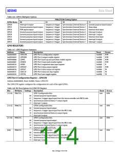
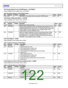
POWER MODES REGISTERS
Table 161. Power Mode Registers Summary
Address
Name
PWRMOD
PWRKEY
Description
Reset
0x0001
0x0000
0x00000000 R/W
0x00000000 R/W
0x00000102 R/W
Access
R/W
R/W
0x00000A00
0x00000A04
0x0000210C
0x00002110
0x00002114
Power mode configuration register
Key protection for PWRMOD register
Key protection for LPMODECLKSEL and LPMODECON registers
LPMODEKEY
LPMODECLKSEL Low power mode clock select register
LPMODECON Low power mode configuration register
Power Modes Register—PWRMOD
Address 0x00000A00, Reset: 0x0001, Name: PWRMOD
Table 162. Bit Descriptions for PWRMOD Register
Bits
Bit Name
Settings Description
Reset Access
15
RAMRETEN
Retention for RAM.
0x0
0x0
0x0
R/W
R/W
R
0
1
RAM is not retained during hibernate mode.
RAM is retained during hibernate mode.
This bit keeps the ADC power switch on in hibernate mode.
ADC power switch turned off during hibernate mode.
ADC power switch turned on during hibernate mode.
Reserved.
14
ADCRETEN
0
1
[13:4] Reserved
Rev. 0 | Page 118 of 130

 ADI [ ADI ]