AD9228
EYE: ALL BITS
EYE: ALL BITS
ULS: 9599/15599
ULS: 10000/15600
400
200
500
0
0
–200
–400
–500
–1ns
–0.5ns
0ns
0.5ns
1ns
–1ns
–0.5ns
0ns
0.5ns
1ns
100
100
50
0
50
0
–150ps –100ps
–50ps
–0ps
50ps
100ps
150ps
–100ps
–0ps
100ps
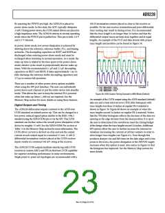
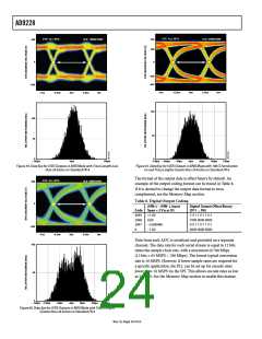
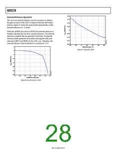
Figure 59. Data Eye for LVDS Outputs in ANSI Mode with Trace Lengths Less
than 24 Inches on Standard FR-4
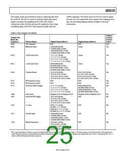
Figure 61. Data Eye for LVDS Outputs in ANSI Mode with 100 Ω Termination
on and Trace Lengths Greater than 24 Inches on Standard FR-4
The format of the output data is offset binary by default. An
example of the output coding format can be found in Table 8.
If it is desired to change the output data format to twos
complement, see the Memory Map section.
EYE: ALL BITS
ULS: 9600/15600
200
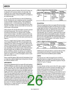
Table 8. Digital Output Coding
(VIN+) − (VIN−), Input
Code Span = 2 V p-p (V)
0
Digital Output Offset Binary
(D11 ... D0)
ꢁ095
20ꢁꢀ
20ꢁꢂ
0
+1.00
1111 1111 1111
1000 0000 0000
0111 1111 1111
0000 0000 0000
0.00
−0.000ꢁꢀꢀ
−1.00
–200
100
–1ns
–0.5ns
0ns
0.5ns
1ns
Data from each ADC is serialized and provided on a separate
channel. The data rate for each serial stream is equal to 12 bits
times the sample clock rate, with a maximum of 780 Mbps
(12 bits × 65 MSPS = 780 Mbps). The lowest typical conversion
rate is 10 MSPS. However, if lower sample rates are required for
a specific application, the PLL can be set up for encode rates
lower than 10 MSPS via the SPI. This allows encode rates as low
as 5 MSPS. See the Memory Map section to enable this feature.
50
0
–150ps –100ps
–50ps
–0ps
50ps
100ps
150ps
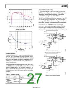
Figure 60. Data Eye for LVDS Outputs in ANSI Mode with Trace Lengths
Greater than 24 Inches on Standard FR-4
Rev. 0 | Page 2ꢁ of 52

 ADI [ ADI ]