AD73360L
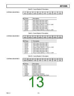
Control Register F
CRF:0–2
Input Gain Selection. These bits select the input gain for ADC5. See Table II.
CRF:3
Power Control for ADC5. A 1 in this bit powers up ADC5.
CRF:4–6
CRF:7
Input Gain Selection. These bits select the input gain for ADC6. See Table II.
Power Control for ADC6. A 1 in this bit powers up ADC6.
Control Register G
CRG:0–5
Channel Select. These bits are used in association with CRG:6 and CRG:7. If the Reset Analog Modulator bit
(CRG:6) is 1, a 1 in a Channel Select bit location will reset the Analog Modulator for that channel. If the Single-
Ended Enable Mode bit (CRG:7) is 1, a 1 in a Channel Select bit location will put that channel into Single-Ended
Mode. If any channel has its Channel Select bit set to 0, the channel will be set for Differentially-Ended Mode and
will not have its analog modulator reset regardless of the state of CRG:6 and CRG:7.
CRG:6
CRG:7
Reset Analog Modulator. Setting this bit to a 1 will reset the Analog Modulators for any channel whose Channel
Select bit (CRG:0–5) is set to 1. This bit should be set to 0 for normal operation.
Single-Ended Enable Mode. Setting this bit to a 1 will enable Single-Ended Mode on any channel whose Channel
Select bit (CRG:0–5) is set to 1. Setting this bit to 0 will select Differentially-Ended Input Mode for all channels.
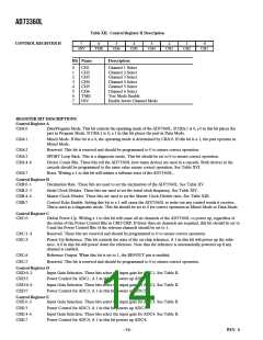
Control Register H
CRH:0–5
Invert Select. These bits are used in association with CRH:7. If the Enable Invert Channel Mode bit (CRH:7) is 1,
a 1 in a Channel Select bit location will put that channel into Inverted Mode. If any channel has its Channel Select
bit set to 0, the channel will not be inverted regardless of the state CRH:7.
CRH:6
CRH:7
Test Mode Enable. This bit should be set to 0 to ensure normal operation.
Enable Invert Channel Mode. Setting this bit to a 1 will enable invert any channel whose Channel Select bit
(CRH:0–5) is set to 1. Setting this bit to 0 will select Noninverted (Normal) Mode for all channels.
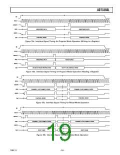
SPORT Register Maps
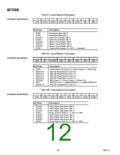
Table XIII. DMCLK (Internal) Rate Divider Settings
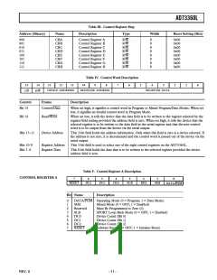
There are eight control registers for the AD73360L, each eight
bits wide. Table III shows the control register map for the
AD73360L. The first two control registers, CRA and CRB, are
reserved for controlling the SPORT. They hold settings for
parameters such as bit rate, internal master clock rate, and device
count. If two AD73360Ls are cascaded, Registers CRA and
CRB on each device must be programmed with the same setting
to ensure correct operation (this is shown in the programming
examples). The other six registers; CRC through CRH are
used to hold control settings for the Reference, Power Control,
ADC channel, and PGA sections of the device. It is not necessary
that the contents of CRC through CRH on each AD73360L
are similar. Control registers are written to on the negative
edge of SCLK.
MCD2
MCD1
MCD0
DMCLK Rate
0
0
0
0
1
1
1
1
0
0
1
1
0
0
1
1
0
1
0
1
0
1
0
1
MCLK
MCLK/2
MCLK/3
MCLK/4
MCLK/5
MCLK
MCLK
MCLK
Serial Clock Rate Divider
The AD73360L features a programmable serial clock divider
that allows users to match the serial clock (SCLK) rate of the
data to that of the DSP engine or host processor. The maximum
SCLK rate available is DMCLK and the other available rates
are: DMCLK/2, DMCLK/4, and DMCLK/8. The slowest rate
(DMCLK/8) is the default SCLK rate. The serial clock divider
is programmable by setting bits CRB:2–3. Table XIV shows the
serial clock rate corresponding to the various bit settings.
Master Clock Divider
The AD73360L features a programmable master clock divider
that allows the user to reduce an externally available master
clock, at pin MCLK, by one of the ratios 1, 2, 3, 4, or 5 to
produce an internal master clock signal (DMCLK) that is used
to calculate the sampling and serial clock rates. The master
clock divider is programmable by setting CRB:4-6. Table XIII
shows the division ratio corresponding to the various bit set-
tings. The default divider ratio is divide-by-one.
Table XIV. SCLK Rate Divider Settings
SCD1
SCD0
SCLK Rate
0
0
1
1
0
1
0
1
DMCLK/8
DMCLK/4
DMCLK/2
DMCLK
–15–
REV. 0

 ADI [ ADI ]