AD73360L
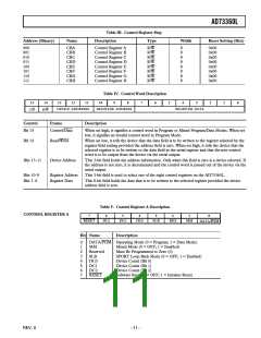
Table III. Control Register Map
Address (Binary)
Name
Description
Type
Width
Reset Setting (Hex)
000
001
010
011
100
101
110
111
CRA
CRB
CRC
CRD
CRE
CRF
CRG
CRH
Control Register A
Control Register B
Control Register C
Control Register D
Control Register E
Control Register F
Control Register G
Control Register H
R/W
R/W
R/W
R/W
R/W
R/W
R/W
R/W
8
8
8
8
8
8
8
8
0x00
0x00
0x00
0x00
0x00
0x00
0x00
0x00
Table IV. Control Word Description
15
14
13
12
11
10
9
8
7
6
5
4
3
2
1
0
DEVICE ADDRESSS
REGISTER ADDRESS
REGISTER DATA
C/D
R/W
Control
Frame
Description
Bit 15
Control/Data
When set high, it signifies a control word in Program or Mixed Program/Data Modes. When set
low, it signifies an invalid control word in Program Mode.
Bit 14
Read/Write
When set low, it tells the device that the data field is to be written to the register selected by the
register field setting provided the address field is zero. When set high, it tells the device that the
selected register is to be written to the data field in the serial register and that the new control
word is to be output from the device via the serial output.
Bits 13–11
Device Address
This 3-bit field holds the address information. Only when this field is zero is a device selected. If
the address is not zero, it is decremented and the control word is passed out of the device via the
serial output.
Bits 10–8
Bits 7–0
Register Address
Register Data
This 3-bit field is used to select one of the eight control registers on the AD73360L.
This 8-bit field holds the data that is to be written to the selected register provided the device
address field is zero.
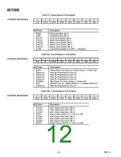
Table V. Control Register A Description
CONTROL REGISTER A
7
6
5
4
3
2
1
0
RESET
DC2
DC1
DC0
SLB
RES
MM
DATA/PGM
Bit Name
Description
0
1
2
3
4
5
6
7
DATA/PGM Operating Mode (0 = Program; 1 = Data Mode)
MM
Reserved
SLB
Mixed Mode (0 = OFF; 1 = Enabled)
Must Be Programmed to Zero (0)
SPORT Loop-Back Mode (0 = OFF; 1 = Enabled)
DC0
Device Count (Bit 0)
DC1
Device Count (Bit 1)
DC2
RESET
Device Count (Bit 2)
Software Reset (0 = OFF; 1 = Initiates Reset)
–11–
REV. 0

 ADI [ ADI ]