AD73360L
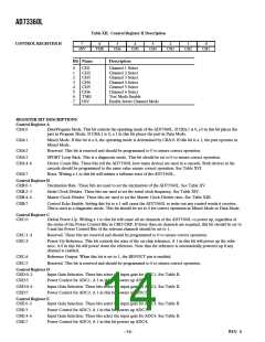
control, the reference will still be enabled; in this case, because
its individual bit is set. Refer to Table VII for details of the settings
of CRC. CRD–CRF can be used to control the power status of
individual channels allowing multiple channels to be powered
down if required.
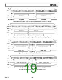
Mixed Program/Data Mode
This mode allows the user to send control words to the device
while receiving ADC words. This permits adaptive control of
the device whereby control of the input gains can be affected by
reprogramming the control registers. The standard data frame
remains 16 bits, but now the MSB is used as a flag bit to indicate
that the remaining 15 bits of the frame represent control infor-
mation. Mixed Mode is enabled by setting the MM bit (CRA:1)
to 1 and the DATA/PGM bit (CRA:0) to 1. In the case where
control setting changes will be required during normal opera-
tion, this mode allows the ability to load control information
with the slight inconvenience of formatting the data. Note that
the output samples from the ADC will also have the MSB set to
zero to indicate it is a data word.
Operating Modes
Three operating modes are available on the AD73360L. They are
Program, Data, and Mixed Program/Data. The device configu-
ration—register settings—can be changed only in Program and
Mixed Program/Data Modes. In all modes, transfers of infor-
mation to or from the device occur in 16-bit packets, therefore
the DSP engine’s SPORT will be programmed for 16-bit transfers.
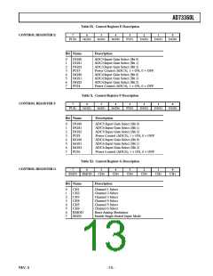
Program (Control) Mode
In Program Mode, CRA:0 = 0, the user writes to the control
registers to set up the device for desired operation—SPORT
operation, cascade length, power management, input gain, etc. In
this mode, the 16-bit information packet sent to the device by
the DSP engine is interpreted as a control word whose format is
shown in Table IV. In this mode, the user must address the device
to be programmed using the address field of the control word. This
field is read by the device and if it is zero (000 bin), the device
recognizes the word as being addressed to it. If the address field
is not zero, it is then decremented and the control word is passed
out of the device—either to the next device in a cascade or back
to the DSP engine. This 3-bit address format allows the user to
uniquely address any one of up to eight devices in a cascade. If
the AD73360L is used in a stand-alone configuration connected
to a DSP, the device address corresponds to 0. If, on the other
hand, the AD73360L is configured in a cascade of two devices,
its device address corresponds with its hardwired position in
the cascade.
A description of a single device operating in mixed mode is
detailed in Appendix B, while Appendix D details the initializa-
tion and operation of an analog front-end cascade operating in
mixed mode. Note that it is not essential to load the control
registers in Program Mode before setting mixed mode active.
Mixed Mode may be selected with the first write by programming
CRA and then transmitting other control words.
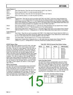
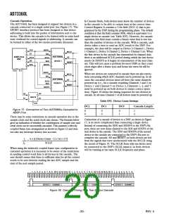
Channel Selection
The ADC channels of the AD73360L can be powered up or
down individually by programming the PUIx bit of registers CRD
to CRF. If the AD73360L is being used in Mixed Data/Control
Mode individual channels may be powered up or down as the
program requires. In Data Mode, the number of channels selected
while the AD73360L was in Program Mode is fixed and cannot
be altered without resetting and reprogramming the AD73360L.
In all cases, ADC Channel 1 must be powered up as the frame
sync pulse generated by this channel defines the start of a new
sample interval.
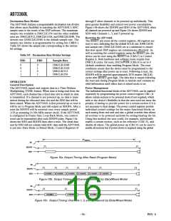
Following reset, when the SE pin is enabled, the AD73360L
responds by raising the SDOFS pin to indicate that an output
sample event has occurred. Control words can be written to the
device to coincide with the data being sent out of the SPORT,
as shown in Figure 12 (Directly Coupled), or they can lag the
output words by a time interval that should not exceed the sample
interval (Indirectly Coupled). Refer to the Digital Interface section
for more information. After reset, output frame sync pulses
will occur at a slower default sample rate, which is DMCLK/
2048, until Control Register B is programmed, after which the
SDOFS will be pulsed at the selected rate. This is to allow
slow controller devices to establish communication with the
AD73360L. During Program Mode, the data output by the
device is random and should not be interpreted as ADC data.
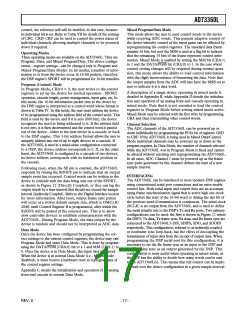
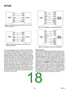
INTERFACING
The AD73360L can be interfaced to most modern DSP engines
using conventional serial port connections and an extra enable
control line. Both serial input and output data use an accompa-
nying frame synchronization signal that is active high one clock
cycle before the start of the 16-bit word or during the last bit of
the previous word if transmission is continuous. The serial clock
(SCLK) is an output from the AD73360L and is used to define
the serial transfer rate to the DSP’s Tx and Rx ports. Two primary
configurations can be used: the first is shown in Figure 11 where
the DSP’s Tx data, Tx frame sync, Rx data, and Rx frame sync are
connected to the AD73360L’s SDI, SDIFS, SDO, and SDOFS
respectively. This configuration, referred to as indirectly coupled
or nonframe sync loop-back, has the effect of decoupling the
transmission of input data from the receipt of output data. When
programming the DSP serial port for this configuration, it is
necessary to set the Rx frame sync as an input to the DSP and
the Tx frame sync as an output generated by the DSP. This
configuration is most useful when operating in mixed mode, as
the DSP has the ability to decide how many words can be sent
to the AD73360L(s). This means that full control can be imple-
mented over the device configuration in a given sample interval.
Data Mode
Once the device has been configured by programming the cor-
rect settings to the various control registers, the device may exit
Program Mode and enter Data Mode. This is done by program-
ming the DATA/PGM (CRA:0) bit to a 1 and MM (CRA:1) to
0. Once the device is in Data Mode, the input data is ignored.
When the device is in normal Data Mode (i.e., Mixed Mode
disabled), it must receive a hardware reset to reprogram any of
the control register settings.
Appendix C details the initialization and operation of an analog
front-end cascade in normal Data Mode.
–17–
REV. 0

 ADI [ ADI ]