AD73360L
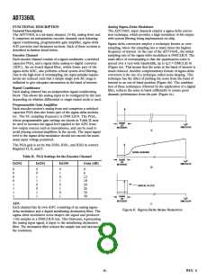
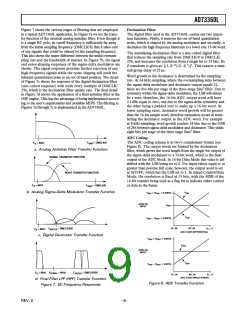
Figure 7 shows the various stages of filtering that are employed
in a typical AD73360L application. In Figure 7a we see the trans-
fer function of the external analog antialias filter. Even though it
is a single RC pole, its cutoff frequency is sufficiently far away
from the initial sampling frequency (DMCLK/8) that it takes care
of any signals that could be aliased by the sampling frequency.
This also shows the major difference between the initial oversam-
pling rate and the bandwidth of interest. In Figure 7b, the signal
and noise-shaping responses of the sigma-delta modulator are
shown. The signal response provides further rejection of any
high-frequency signals while the noise-shaping will push the
inherent quantization noise to an out-of-band position. The detail
of Figure 7c shows the response of the digital decimation filter
(sinc-cubed response) with nulls every multiple of DMCLK/
256, which is the decimation filter update rate. The final detail
in Figure 7d shows the application of a final antialias filter in the
DSP engine. This has the advantage of being implemented accord-
ing to the user’s requirements and available MIPS. The filtering in
Figures 7a through 7c is implemented in the AD73360L.
Decimation Filter
The digital filter used in the AD73360L carries out two impor-
tant functions. Firstly, it removes the out-of-band quantization
noise, which is shaped by the analog modulator and secondly, it
decimates the high-frequency bitstream to a lower rate 15-bit word.
The antialiasing decimation filter is a sinc-cubed digital filter
that reduces the sampling rate from DMCLK/8 to DMCLK/
256, and increases the resolution from a single bit to 15 bits. Its
Z transform is given as: [(1–Z–32)/(1–Z–1)]3. This ensures a mini-
mal group delay of 25 µs.
Word growth in the decimator is determined by the sampling
rate. At 64 kHz sampling, where the oversampling ratio between
the sigma-delta modulator and decimator output equals 32,
there are five bits per stage of the three-stage Sinc3 filter. Due to
symmetry within the sigma-delta modulator, the LSB will always
be a zero; therefore, the 16-bit ADC output word will have
2 LSBs equal to zero, one due to the sigma-delta symmetry and
the other being a padded zero to make up a 16-bit word. At
lower sampling rates, decimator word growth will be greater
than the 16-bit sample word, therefore truncation occurs in trans-
ferring the decimator output as the ADC word. For example
at 8 kHz sampling, word growth reaches 24 bits due to the OSR
of 256 between sigma-delta modulator and decimator. This yields
eight bits per stage of the three stage Sinc3 filter.
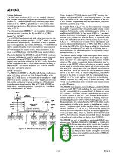
ADC Coding
F
= DMCLK/8
The ADC coding scheme is in two’s complement format (see
Figure 8). The output words are formed by the decimation
filter, which grows the word length from the single-bit output of
the sigma-delta modulator to a 15-bit word, which is the final
output of the ADC block. In 16-bit Data Mode this value is left
shifted with the LSB being set to 0. For input values equal to or
greater than positive full scale, however, the output word is set
at 0x7FFF, which has the LSB set to 1. In mixed Control/Data
Mode, the resolution is fixed at 15 bits, with the MSB of the
16-bit transfer being used as a flag bit to indicate either control
or data in the frame.
F
= 4kHz
SINIT
B
a. Analog Antialias Filter Transfer Function
SIGNAL TRANSFER FUNCTION
NOISE TRANSFER FUNCTION
F
= 4kHz
F
= DMCLK/8
B
SINIT
b. Analog Sigma-Delta Modulator Transfer Function
V
V
+ (V
REF
INN
REF
ANALOG
INPUT
V
REF
V
INP
V
– (V
REF
REF
10...00
00...00
ADC CODE DIFFERENTIAL
F
= DMCLK/256
01...11
F
= 4kHz
SINTER
B
c. Digital Decimator Transfer Function
V
+ (V
REF
REF
V
INN
ANALOG
INPUT
V
INP
V
REF
REF
F
= 4kHz
F
= 8kHz
F
= DMCLK/256
SFINAL
B
SINTER
10...00
00...00
ADC CODE SINGLE-ENDED
01...11
d. Final Filter LPF (HPF) Transfer Function
Figure 7. DC Frequency Responses
Figure 8. ADC Transfer Function
–9–
REV. 0

 ADI [ ADI ]