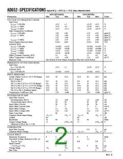
(typical @ T = +25؇C, V = ؎15 V, unless otherwise noted)
AD652–SPECIFICATIONS
A
S
AD652JP/AQ/SQ
Typ
AD652KP/BQ
Typ
Parameter
Min
Max
Min
Max
Units
VOLTAGE-TO-FREQUENCY MODE
Gain Error
fCLOCK = 200 kHz
0.5
0.5
0.5
1
؎1
؎1.5
0.25
0.25
0.25
0.5
؎0.5
؎0.75
%
%
%
f
f
CLOCK = 1 MHz
CLOCK = 4 MHz
Gain Temperature Coefficient
fCLOCK = 200 kHz
25
25
10
25
0.001
50
؎50
؎50
؎75
0.01
15
15
10
15
0.001
25
؎25
؎30
؎50
0.01
ppm/°C
ppm/°C
ppm/°C1
ppm/°C
%/V
f
CLOCK = 1 MHz
fCLOCK = 4 MHz
Power Supply Rejection Ratio
Linearity Error
fCLOCK = 200 kHz
0.002
0.002
0.01
0.02
1
0.02
؎0.02
0.02
؎0.05
؎3
0.002
0.002
0.002
0.01
1
0.005
؎0.005
0.005
؎0.02
؎2
%
%
%
%
mV
µV/°C
f
CLOCK = 1 MHz
fCLOCK = 2 MHz
CLOCK = 4 MHz
f
Offset (Transfer Function, RTI)
Offset Temperature Coefficient
Response Time
10
؎50
10
؎25
One Period of New Output Frequency Plus One Clock Period.
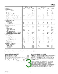
FREQUENCY-TO-VOLTAGE MODE
Gain Error
f
IN = 100 kHz FS
0.5
1
0.25
0.5
%
%
Linearity Error
fIN = 100 kHz FS
0.002
0.02
0.002
0.01
INPUT RESISTORS
Cerdip (Figure 1a)(0 to +10 V FS Range)
PLCC (Figure lb)
Pin 8 to Pin 7
Pin 7 to Pin 5 (0 V to +5 V FS Range)
Pin 8 to Pin 5 (0 V to +10 V FS Range)
Pin 9 to Pin 5 (0 V to +8 V FS Range)
Pin 10 to Pin 5 (Auxiliary Input)
Temperature Coefficient (All)
19.8
20
20.2
19.8
20
20.2
kΩ
9.9
9.9
19.8
15.8
19.8
10
10
20
16
20
10.1
10.1
20.2
16.2
20.2
؎100
9.9
9.9
19.8
15.8
19.8
10
10
20
16
20
10.1
10.1
20.2
16.2
20.2
؎100
kΩ
kΩ
kΩ
kΩ
kΩ
50
50
ppm/°C
INTEGRATOR OP AMP
Input Bias Current
Inverting Input (Pin 5)
Noninverting Input (Pin 6)
Input Offset Current
Input Offset Current Drift
Input Offset Voltage
Input Offset Voltage Drift
Open Loop Gain
5
20
20
1
1
10
؎20
50
70
3
؎3
5
20
20
1
1
10
؎20
50
70
2
؎2
nA
nA
nA
nA/°C
mV
µV/°C
dB
25
15
86
86
Common-Mode Input Range
CMRR
–VS + 5
80
+VS – 5
–VS + 5
80
+VS – 5
V
dB
Bandwidth
14
95
14
95
MHz
Output Voltage Range
–1
(+VS – 4)
–1
(+VS – 4) V
(Referred to Pin 6, R1 > = 5k)
COMPARATOR
Input Bias Current
Common-Mode Voltage
0.5
5
0.5
5
µA
V
–VS + 4
+ VS – 4
–VS + 4
+VS – 4
CLOCK INPUT
Maximum Frequency
Threshold Voltage (Referred to Pin 12)
TMIN to TMAX
4
5
1.2
4
5
1.2
MHz
V
V
0.8
2.0
0.8
2.0
Input Current
(–VS<VCLK< +VS)
Voltage Range
Rise Time
5
20
+VS
2
5
20
+VS
2
µA
V
µs
–VS
–VS
–2–
REV. B

 ADI [ ADI ]