OX9162
OXFORD SEMICONDUCTOR LTD.
4.5 PCI Interrupts
Interrupts in PCI systems are level-sensitive and can be
shared. There are three sources of interrupt in the OX9162,
two from Multi-Purpose IO pins (MIO1 to MIO0) and one
from the parallel port. The Local Bus uses the MIO pins to
pass interrupts to the PCI controller.
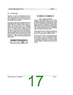
2 to 255
Reserved
Table 6: ‘Interrupt pin’ definition
During the system initialisation process and PCI device
configuration, system-specific software reads the interrupt
pin field to determine which (if any) interrupt pin is used by
the function. It programmes the system interrupt router to
logically connect this PCI interrupt pin to a system-specific
interrupt vector (IRQ). It then writes this routing information
to the Interrupt Line field in the function’s PCI configuration
space. Device driver software must then hook the interrupt
using the information in the Interrupt Line field.
All interrupts are routed to the PCI interrupt pin INTA#. The
default routing asserts Function0 interrupts on INTA#. This
default routing may be modified (to disable interrupts) by
writing to the Interrupt Pin field in the configuration
registers using the serial EEPROM facility. The Interrupt
Pin field is normally considered a hard-wired read-only
value in PCI. It indicates to system software which PCI
interrupt pin (if any) is used by a function. The interrupt pin
may only be modified using the serial EEPROM facility,
and card developers must not set any value which violates
the PCI specification. Note that OX9162 only has one PCI
interrupt pin - INTA#. If in doubt, the default routings
should be used. Table 6 relates the Interrupt Pin field to the
device pin used.
Interrupt status for all sources of interrupt is available using
the GIS register in the Local Configuration Register set,
which can be accessed using I/O or Memory accesses.
All interrupts can be enabled / disabled individually using
the GIS register set in the Local configuration registers.
When an MIO pin is enabled, an external device can assert
a PCI interrupt by driving that pin. The sense of the MIO
external interrupt pins (active-high or active-low) is defined
in the MIC register. The parallel port can also assert an
interrupt.
Interrupt Pin
Device Pin used
None
0
1
INTA#
Data Sheet Revision 1.1 PRELIMINARY
Page 17

 OXFORD [ OXFORD SEMICONDUCTOR ]