FEDL87V2107-01
OKI Semiconductor
ML87V2107
1.2.4 Setting an Output Internal Sync. Signal Mode
By setting the external pin to INT = 1 or the I2C-bus setting register to IINT (SUB:68h-bit[6]) = 1, Sync. signals
from the internal Sync. signal generating circuit can be used as OVS and OHS for read memory control.
In this case, the OVS and OHS pins are configured as output pins.
Table F1-2-4 Output Sync. Signal Select Mode
INT or IINT
OVS
Input
OHS
Input
Remarks
0
1
The external Sync. signal is used.
The internal Sync. signal generator is used.
Output
Output
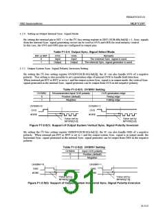
1.2.5 Output System Sync. Signal Polarity Inversion Setting
By setting the I2C-bus setting register OVSINV(SUB:61h-bit[0]), the IC can also handle OVS of a negative
polarity. This setting is also possible to set a generation edge of internal OVR to handle field detection.
When external pin INT or IINT is set to 1 and the output system Sync. signal is in output mode, the vertical Sync.
signal generated in the internal Sync. signal generator can be output from OVS in the negative polarity.
Table F1-2-5(1) OVSINV Setting
OVSINV
Recommended input OHS polarity
Positive (default)
OVR generation edge
Rising edge
0
1
Negative
Falling edge
OVSINV=0
OVSINV=1
OVS
OVS
#ORE
#ORE
Value set by
NPVRE[3:0]
Value set by
NPVRE[3:0]
Figure F1-2-5(1) Support of Output System Vertical Sync. Signal Polarity Inversion
By setting the I2C-bus setting register OHSINV(SUB:61h-bit[1]), the IC can also handle OHS of a negative
polarity. When external pin INT or IINT is set to 1 and the output system Sync. signal is in output mode, the
horizontal Sync. signal generated in the internal Sync. signal generator can be output from OHS in the negative
polarity.
Table F1-2-5(2) OHSINV Setting
OHSINV
Input OHS polarity
Positive (default)
Negative
0
1
OHSINV=0
OHS
OHSINV=1
OHS
#ORE
#ORE
Value set by
NPHRE[7:0]
Value set by
NPHRE[7:0]
Figure F1-2-5(2) Support of Output System Horizontal Sync. Signal Polarity Inversion
31/152

 OKI [ OKI ELECTRONIC COMPONETS ]