VT82C686B
Offset 5A – KBC / RTC Control......................................RW
Offset 5B - Internal RTC Test Mode .............................. RW
Bits 7-4 of this register are latched from pins SD7-4 at power-
up but are read/write accessible so may be changed after
power-up to change the default strap setting:
........................................always reads 0
Map RTC Rx32 to Rx3F
Disable................................................... default
Enable
RTC Reset Enable (do not program)
Disable................................................... default
Enable
RTC SRAM Access Enable
7-4 Reserved
3
2
1
0
1
............................. latched from SD7
............................ latched from SD6
............................ latched from SD5
............................ latched from SD4
7
6
5
4
3
Keyboard RP16
Keyboard RP15
Keyboard RP14
Keyboard RP13
0
1
Audio Function Enable
....... RO, strapped from SPKR pin V5
0
1
Disable................................................... default
Enable
0
Disable (SDD pins function as SDD)
This bit is set if the internal RTC is disabled but it is
desired to still be able to access the internal RTC
SRAM via ports 74-75. If the internal RTC is
enabled, setting this bit does nothing (the internal
RTC SRAM should be accessed at either ports 70/71
or 72/73.
1
Enable (SDD pins function as Audio / Game)
2
1
0
Internal RTC Enable
0
Disable
1
Enable ....................................................default
Internal PS2 Mouse Enable
0
Disable ..................................................default
0
RTC Test Mode Enable (do not program) .default=0
1
Enable
Internal KBC Enable
Offset 5C - DMA Control................................................. RW
0
Disable ..................................................default
7
6
5
4
PCS0# & PCS1# 16-Bit I/O
1
Enable
0
1
Disable................................................... default
Enable
Passive Release
Disable................................................... default
Enable
Internal Passive Release
Disable................................................... default
Enable
Dummy PREQ
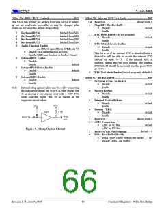
Note: External strap option values may be set by connecting
the indicated external pin to a 4.7K ohm pullup (for
1) or driving it low during reset with a 7407 TTL
open collector buffer (for 0) as shown in the
suggested circuit below:
0
1
0
1
0
1
Disable................................................... default
Enable
3
2
Reserved
........................................always reads 0
APIC Connection
0
1
APIC on SD Bus.................................... default
APIC on XD Bus
Figure 5. Strap Option Circuit
1
0
Reserved (Do Not Program) ....................default = 0
DMA Line Buffer Disable
0
1
DMA cycles can be to/from line buffer .......def
Disable DMA Line Buffer
Revision 1.71 June 9, 2000
-60-
Function 0 Registers - PCI to ISA Bridge

 ETC [ ETC ]