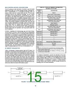
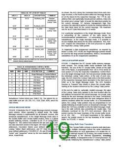
As shown, the ACE stores the Command Word from each mes-
sage received, in the fourth location within the message descrip-
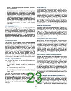
TABLE 28. RT LOOK-UP TABLES
AREA A
AREA B
DESCRIPTION
COMMENT
T/R
tor (in the stack) for the respective message. The
bit, sub-
0140
.
.
.
01C0
Rx(/Bcst)_SA0
Receive
(/Broadcast)
Lookup Table
address field, and (optionally) broadcast/own address, index into
the active area Lookup Table, to locate the data block pointer for
the current message. RT memory management logic then
accesses the data block pointer to locate the starting address for
the Data Word block for the current message. The maximum
size for an RT Data Word block is 32 words.
.
.
.
.
.
.
015F
01DF
Rx(/Bcst)_SA31
0160
.
01E0
Tx_SA0
Transmit
Lookup Table
.
.
.
.
.
.
.
.
For a particular subaddress in the Single Message mode, there
is overwriting of the contents of the data blocks for
receive/broadcast subaddresses – or overreading, for transmit
subaddresses. In the single message mode, it is possible to
access multiple data blocks for the same subaddress. This, how-
ever, requires the intervention of the host processor to update
the respective Lookup Table pointer.
017F
01FF
Tx_SA31
0180
.
.
.
0200
.
.
.
Bcst_SA0
Broadcast
Lookup Table
(Optional)
.
.
.
019F
021F
Bcst_SA31
01A0
.
.
.
0220
.
.
.
SACW_SA0
Subaddress
Control Word
Lookup Table
(Optional)
To implement a data wraparound subaddress, as required by
Notice 2 of MIL-STD-1553B, the Single Message scheme should
be used for the wrap-around subaddress. Notice 2 recommends
subaddress 30 as the wraparound subaddress.
.
.
.
01BF
023F
SACW_SA31
Note: Address represents the word offset from the memory base address in the
common memory address space.
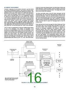
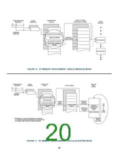
CIRCULAR BUFFER MODE
FIGURE 11 illustrates the RT circular buffer memory manage-
ment scheme. The circular buffer mode facilitates bulk data
transfers. The size of the RT circular buffer, shown on the right
side of the figure, is programmable from 128 to 8192 words (in
even powers of 2) by the respective Subaddress Control Word.
As in the single message mode, the host processor initially loads
the individual Lookup Table entries. At the start of each mes-
sage, the ACE stores the Lookup Table entry in the third position
of the respective message block descriptor in the stack area of
RAM, as in the Single Message mode. The ACE transfers
Receive or Transmit Data Words to (from) the circular buffer,
starting at the location referenced by the Lookup Table pointer.
TABLE 29. SUBADDRESS CONTROL WORD
Memory Management Subaddress Buffer Scheme
MM2
MM1
MM0
DESCRIPTION
COMMENT
0
0
0
0
1
1
1
1
0
0
1
1
0
0
1
1
0
1
0
1
0
1
0
1
Single Message or Double Buffered
Circular Buffer of
Specified Size
128-Word
256-Word
512-Word
1024-Word
2048-Word
4096-Word
8192-Word
At the end of a valid (or, optionally, invalid) message, the value
of the Lookup Table entry updates to the next location after the
last address accessed for the current message. As a result, Data
Words for the next message directed to the same Tx/RX(/Bcst)
subaddress will be accessed from the next contiguous block of
address locations within the circular buffer. As a recommended
option, the Lookup Table pointers may be programmed to not
update following an invalid receive (or broadcast) message. This
allows the 1553 bus controller to retry the failed message, result-
ing in the valid (retried) data overwriting the invalid data. This
eliminates overhead for the RT's host processor. When the
pointer reaches the lower boundary of the circular buffer (locat-
ed at 128-, 256-, . . . 8192-word boundaries in the address
space), the pointer moves to the top boundary of the circular
buffer, as FIGURE 11 shows.
Subaddress Control Word (see TABLE 29). The options for cir-
cular buffer size are 128, 256, 512, 1024, 2048, 4096, and 8192
Data Words.
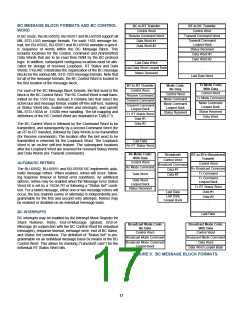
SINGLE MESSAGE MODE
FIGURE 10 illustrates the RT Single Message memory manage-
ment scheme. When operating in default mode, the Single
Message scheme is implemented for all transmit, receive, and
broadcast subaddresses. In the Single Message mode (also in
the Double Buffer and Circular Buffer modes), there is a global
double buffering scheme, controlled by bit 13 of Configuration
Register #1. This selects from between the two sets of the vari-
ous data structures shown in the figure: the Stack Pointers (fixed
addresses), Descriptor Stacks (user defined addresses), RT
Lookup Tables (fixed addresses), and RT Data Word blocks
(user defined addresses). FIGURES 27, 28, and 29 delineate the
"active" and "nonactive" areas by the non-shaded and shaded
areas, respectively.
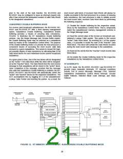
Implementing Bulk Data Transfers
The use of the Circular Buffer scheme is ideal for bulk data trans-
fers; that is, multiple messages to/from the same subaddress.
The recommendation for such applications is to enable the cir-
cular buffer interrupt request. By so doing, the routine transfer of
multiple messages to the selected subaddress, including
errors and retries, is transparent to the RT's host processor. By
strategically initializing the subaddresses' Lookup Table pointer
19

 ETC [ ETC ]