BUS CONTROLLER (BC) ARCHITECTURE
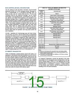
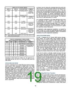
TABLE 26. TYPICAL BC MEMORY ORGANIZATION
(SHOWN FOR 12K RAM)
The BC protocol of the BU-65552, BU-65551 and BU-65550
implement all MIL-STD-1553B message formats. Message for-
mat is programmable on a message-by-message basis by
ADDRESS
DESCRIPTION
(HEX)
0000-00FF
0100
Stack A
T/R
means of bits in the BC Control Word and the
bit of the
Command Word for the respective message. The BC Control
Word allows 1553 message format, 1553A/B type RT, bus chan-
nel, self-test, and Status Word masking to be specified on an
individual message basis. In addition, automatic retries and/or
interrupt requests may be enabled or disabled for individual mes-
sages. The BC performs all error checking required by MIL-STD-
1553B. This includes validation of response time, sync type and
sync encoding, Manchester II encoding, parity, bit count, word
count, Status Word RT Address field, and various RT-to-RT
transfer errors. The BC response timeout value is programma-
ble with choices of 18, 22, 50, and 130 µs. The longer response
timeout values allow for operation over long buses and/or the
use of repeaters.
Stack Pointer A (fixed location)
Message Count A (fixed location)
0101
Initial Stack Pointer A (see note)
(Auto-Frame Repeat Mode)
0102
0103
Initial Message Count A (see note)
(Auto-Frame Repeat Mode)
0104
0105
Stack Pointer B
Message Count B
Initial Stack Pointer B (see note)
(Auto-Frame Repeat Mode)
0106
0107
Initial Message Count B (see note)
(Auto-Frame Repeat Mode)
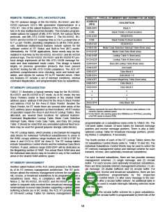
FIGURE 7 illustrates BC intermessage gap and frame timing.
The BU-65552, BU-65551 and BU-65550 may be programmed
to process BC frames of up to 512 messages with no processor
intervention. It is possible to program for either single frame or
frame auto-repeat operation. In the auto-repeat mode, the frame
repetition rate may be controlled either internally, using a pro-
grammable BC frame timer, or from an external trigger input. The
internal BC frame time is programmable up to 6.55 seconds in
increments of 100 µs. In addition to BC frame time, intermessage
gap time, defined as the start of the current message to the start
of the subsequent message, is programmable on an individual
message basis. The time between individual successive mes-
sages is programmable up to 65.5 ms, in increments of 1 µs.
0108-012D
012E-0153
0154-0179
•
Message Block 0
Message Block 1
Message Block 2
•
•
•
•
•
Message Block 308Message Block 8
Not Used
2EC0-2EE5
2EE6-2EFF
2F00-2FFF
Stack B
Notes:
1) Used only in the Enhanced BC mode with Frame Auto-Repeat enabled.
2) Address represents the word offset from the memory base address in the
common memory address space.
3) For the 65552, the memory spans from 0000(hex) to FFFF(hex), providing
a full 64K words of shared RAM.
BC MEMORY ORGANIZATION
TABLE 26 illustrates a typical memory map for BC mode. It is
important to note that the only fixed locations for the BU-65552,
BU-65551 and BU-65550 in the Standard BC mode are for the
two Stack Pointers (address locations 0100 [hex] and 0104) and
for the two Message Count locations (0101 and 0105). Enabling
the Frame Auto-Repeat mode will reserve four more memory
locations for use in the Enhanced BC mode; these locations are
for the two Initial Stack Pointers (address locations 102 [hex] and
106) and for the Initial Message Count locations (103 and 107).
The user is free to locate the Stack and BC Message Blocks any-
where else within the shared RAM address space.
For simplicity of illustration, assume the allocation of the maxi-
mum length of a BC message for each message block in the typ-
ical BC memory map of TABLE 26. The maximum size of a BC
message block is 38 words, for an RT-to-RT transfer of 32 Data
Words (Control + 2 Commands + Loopback + 2 Status Words +
32 Data Words). Note, however, that this example assumes the
disabling of the 256-word boundaries.
INTERMESSAGE
GAP TIME
FOR MESSAGE NO. 1
MESSAGE NO. 2
MESSAGE NO. 1
MESSAGE NO. 1
BC FRAME TIME
FIGURE 7. BC MESSAGE GAP AND FRAME TIMING
15

 ETC [ ETC ]