REMOTE TERMINAL (RT) ARCHITECTURE
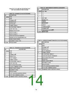
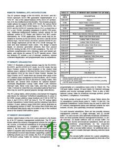
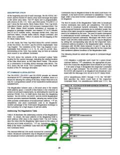
TABLE 27. TYPICAL RT MEMORY MAP (SHOWN FOR 12K RAM)
ADDRESS
DESCRIPTION
(HEX)
The RT protocol design of the BU-65552, BU-65551 and BU-
65550 represent DDC's fifth generation implementation of a
1553 RT. One of the salient features of the ACE's RT architec-
ture is its true multiprotocol functionality. This includes program-
mable options for support of MIL-STD-1553A, the various McAir
protocols, and MIL-STD-1553B Notice 2. The BU-65552, BU-
65551 and BU-65550 RT response time is 2 to 5 µs dead time (4
to 7 µs per 1553B), providing compliance to all the 1553 proto-
cols. Additional multiprotocol features include options for full
software control of RT Status and Built-in-Test (BIT) words.
Alternatively, for 1553B applications, these words may be for-
mulated in real-time by the BU-65552, BU-65551 and BU-65550
protocol logic. The BU-65552, BU-65551 and BU-65550 RT pro-
tocol design implements all the MIL-STD-1553B message for-
mats and dual redundant mode codes. This design is based
largely on previous generation products that have passed
SEAFAC testing for MIL-STD-1553B compliance. The ACE RT
performs comprehensive error checking, word and format vali-
dation, and checks for various RT-to-RT transfer errors. Other
key features RT include a set of interrupt conditions, internal
command illegalization, and programmable busy by subaddress.
0000-00FF
0100
Stack A
Stack Pointer A (fixed location)
0101-0103
0104
RESERVED
Stack Pointer B (fixed location)
0105-0107
0108-010F
0110-013F
0140-01BF
01C0-023F
0240-0247
0248-025F
0260-027F
0280-02FF
0300-03FF
0400-041F
0420-043F
·•
RESERVED
Mode Code Selective Interrupt Table (fixed area)
Mode Code Data (fixed area)
Lookup Table A (fixed area)
Lookup Table B (fixed area)
Busy Bit Lookup Table (fixed area)
(not used)
Data Block 0
Data Block 1-4
Command Illegalizing Table (fixed area)
Data Block 5
Data Block 6
RT MEMORY ORGANIZATION
•
TABLE 27 illustrates a typical memory map for the BU-65552,
BU-65551 and BU-65550 in RT mode. As in BC mode, the two
Stack Pointers reside in fixed locations in the shared RAM
address space: address 0100 (hex) for the Area A Stack Pointer
and address 0104 for the Area B Stack Pointer. Besides the
Stack Pointer, for RT mode there are several other areas of the
ACE address space designated as fixed locations. All RT modes
of operation require the Area A and Area B Lookup Tables. Also
allocated, are several fixed locations for optional features:
Command Illegalization Lookup Table, Mode Code Selective
Interrupt Table, Mode Code Data Table, and Busy Bit Lookup
Table. It should be noted that any unenabled optional fixed loca-
tions may be used for general purpose storage (data blocks).
•
•
•
•
2FE0-2FFF
Data Block 356
Notes:
1) Address represents the word offset from the memory base address in the
common memory address space.
3) For the 65552, the memory spans from 0000(hex) to FFFF(hex), providing
a full 64K words of shared RAM.
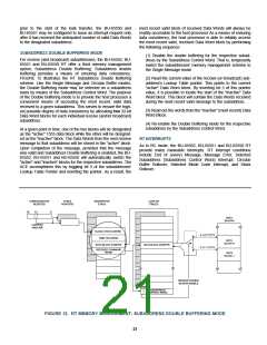
programmable on a subaddress basis (refer to TABLE 28). The
128-word tables include 32-word tables for transmit message
pointers and receive message pointers. There is also a third,
optional Lookup Table for broadcast message pointers, provid-
ing Notice 2 compliance, if necessary.
The RT Lookup tables, which provide a mechanism for mapping
data blocks for individual Tx/Rx/Bcst-subaddresses to areas in
the RAM, occupy address range locations are 0140 to 01BF for
Area A and 01C0 to 023F for Area B. The RT lookup tables
include Subaddress Control Words and the individual Data Block
Pointers. If used, address range 0300-03FF will be dedicated as
the illegalizing section of RAM. The actual Stack RAM area and
the individual data blocks may be located in any of the nonfixed
areas in the shared RAM address space.
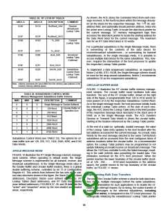
The fourth section of each of the RT Lookup Tables stores the
32 Subaddress Control Words (refer to TABLE 10 and 28). The
individual Subaddress Control Words may be used to select the
RT memory management option and interrupt scheme for each
transmit, receive, and (optionally) broadcast subaddress.
For each transmit subaddress, there are two possible memory
management schemes: (1) single message; and (2) circular
buffer. For each receive (and optionally broadcast) subaddress,
there are three possible memory management schemes: (1) sin-
gle message; (2) double buffered; and (3) circular buffer. For
each transmit, receive and broadcast subaddress, there are two
interrupt conditions programmable by the respective
Subaddress Control Word: (1) after every message to the sub-
address; (2) after a circular buffer rollover. An additional table in
RAM may be used to enable interrupts following selected mode
code messages.
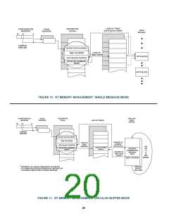
RT MEMORY MANAGEMENT
Another salient feature of the ACE series products is the flexibil-
ity of its RT memory management architecture. The RT archi-
tecture allows the memory management scheme for each trans-
mit, receive, or broadcast subaddress to be programmable on a
subaddress basis. Also, in compliance with MIL-STD-1553B
Notice 2, the BU-65552, BU-65551 and BU-65550 provide an
option to separate data received from broadcast messages from
nonbroadcast received data.Besides supporting a global double
buffering scheme (as in BC mode), the ACE RT provides a pair
of 128-word Lookup Tables for memory management control,
When using the circular buffer scheme for a given subaddress,
the size of the circular buffer is programmable by three bits of the
18

 ETC [ ETC ]