BC MEMORY MANAGEMENT
In the BC Frame Auto-Repeat mode, the Initial Stack Pointer and
Initial Message Counter locations must be loaded by the host
prior to the processing of the first frame. The single frame mode
does not use these two locations.
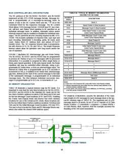
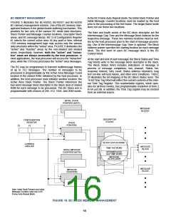
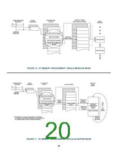
FIGURE 8 illustrates the BU-65552, BU-65551 and BU-65550
BC memory management scheme. One of the BC memory man-
agement features is the global double buffering mechanism. This
provides for two sets of the various BC mode data structures:
Stack Pointer and Message Counter locations, Descriptor Stack
areas, and BC message blocks. Bit 13 of Configuration Register
#1 selects the current active area. At any point in time, internal
1553 memory management logic may access only the various
data structures within the "active" area. FIGURE 8 delineates the
"active" and "inactive" areas by the non-shaded and shaded
areas, respectively; however, both the "active" and "nonac-
tive" areas are always accessible by the host processor. In
most applications, the host processor will access the "nonactive"
area, while the 1553 bus processes the "active" area messages.
The third and fourth words of the BC block descriptor are the
Intermessage Gap Time and the Message Block Address for the
respective message. These two memory locations must be writ-
ten by the host processor prior to the start of message process-
ing. Use of the Intermessage Gap Time is optional. The Block
Address pointer specifies the starting location for each message
block. The first word of each BC message block is the BC
Control Word.
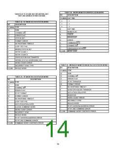
At the start and end of each message, the Block Status and Time
Tag Words write to the message block descriptor in the stack.
The Block Status Word includes indications of message in
process or message completion, bus channel, Status Set,
response timeout, retry count, Status address mismatch, loop
test (on-line self-test) failure, and other error conditions. TABLE
22 illustrates the bit mapping of the BC Block Status word. The
16-bit Time Tag Word will reflect the current contents of the inter-
nal Time Tag Register. This read/writable register, which oper-
ates for all three modes, has programmable resolution of from 2
to 64 µs/LSB. In addition, the Time Tag register may be clocked
from an external source.
The BC may be programmed to transmit multimessage frames
of up to 512 messages. The number of messages to be
processed is programmable by the Active Area Message Count
location in the shared RAM, initialized by the host processor. In
addition, the host processor must initialize another location, the
Active Area Stack Pointer. The Stack Pointer references the
four-word message block descriptor in the Stack area of shared
RAM for each message to be processed. The BC Stack size is
programmable with choices of 256, 512, 1024, and 2048 words.
INITIAL STACK
POINTERS (NOTE)
MESSAGE
BLOCKS
DESCRIPTOR
STACKS
CONFIGURATION
REGISTER
STACK
POINTERS
15
13
0
BLOCK STATUS WORD
CURRENT
AREA B/A
MESSAGE
TIME TAG WORD
BLOCK
INITIAL MESSAGE
COUNTERS (NOTE)
INTERMESSAGE
GAP TIME WORD
MESSAGE
BLOCK ADDR
MESSAGE
BLOCK
MESSAGE
COUNTERS
Note: Initial Stack Pointers and Initial
Message Counters used only in BC
Frame Auto-Repeat Mode.
FIGURE 18. BC MODE MEMORY MANAGEMENT
16

 ETC [ ETC ]