"WC/MC" field specifies the Mode Code field of the respec-
tive Command Word.
WORD MONITOR
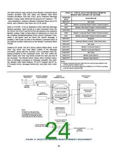
In the Word Monitor mode, the BU-65552, BU-65551 and BU-
65550 monitor both 1553 buses. After initializing the Word
Monitor and putting it on-line the BU-65552, BU-65551 and BU-
65550 store all Command, Status, and Data Words received
from both buses. For each word received from either bus, a pair
of words are stored in shared RAM. The first word is the 16 bits
of data from the received word. The second word is the Monitor
Identification (ID), or "Tag" word. The ID Word contains informa-
tion relating to bus channel, sync type, word validity, and inter-
word time gaps. The BU-65552, BU-65551 and BU-65550 store
data and ID words in a circular buffer in the shared RAM address
space. TABLE 24 shows the bit mapping for the Monitor ID word.
(3)Since nonmode code broadcast transmit messages are
not defined by MIL-STD-1553B, the 60 words in the illegal-
ization RAM, addresses 0342 through 037D, corresponding
to these commands do not need to be initialized. They will
not respond to a non-mode code broadcast transmit com-
mand, but will automatically set the Message Error bit in its
internal Status Register, regardless of whether or not corre-
sponding bit in the illegalization RAM has been set. If the
next message is a Transmit Status or Transmit Last
Command mode code, they will respond with its Message
Error bit set.
MONITOR TRIGGER WORD
PROGRAMMABLE BUSY
There is a Trigger Word Register that provides additional flexi-
bility for the Word Monitor mode. The BU-65552, BU-65551 and
BU-65550 store the value of the 16-bit Trigger Word in the MT
Trigger Word Register. The contents of this register represent
the value of the Trigger Command Word. There are programma-
ble options to start or stop the Word Monitor, and/or to issue an
interrupt request following receipt of the Trigger Command Word
from the 1553 bus.
As a means of providing compliance with Notice 2 of MIL-STD-
1553B, the BU-65552, BU-65551 and BU-65550 RT provide a
software controllable means for setting the Busy Status Word bit
as a function of subaddress. By a Busy Lookup Table in the
shared RAM space, it is possible to set the Busy bit based on
T/R
command broadcast/own address,
bit, and subaddress.
Another programmable option, allows received Data Words to be
either stored or not stored for messages, when the Busy bit is
set.
SELECTIVE MESSAGE MONITOR MODE
The BU-65552, BU-65551 and BU-65550 Selective Message
Monitor provide features to greatly reduce the software and pro-
cessing burden of the host CPU. The Selective Message Monitor
implements selective monitoring of messages from a dual 1553
OTHER RT FUNCTIONS
The BU-65552, BU-65551 and BU-65550 allow the hardwired
RT Address to be read by the host processor. Also, there are
options for the RT FLAG Status Word bit to be set under soft-
ware control and/or automatically following a failure of the loop-
back self-test. Other software controllable RT options include
software programmable RT Status and RT BIT words, automat-
ic clearing of the Service Request Status Word bit following a
Transmit Vector Word mode command, capabilities to clear
and/or load the Time Tag Register following receipt of
Synchronize mode commands, options regarding Data Word
transfers for the Busy and/or Message Error (Illegal) Status
Word bits, and for handling of 1553A and reserved mode codes.
T/R
bus, with the monitor filtering based on the RT Address,
bit,
and Subaddress fields of received 1553 Command Words. The
Selective Message Monitor mode greatly simplifies the host
processor software by distinguishing between Command and
Status Words. The Selective Message Monitor maintains two
stacks in RAM: a Command Stack and a Data Stack.
SIMULTANEOUS RT/MESSAGE MONITOR MODE
The Selective Message Monitor may function as a purely passive
monitor or may be programmed to function as a simultaneous
RT/Monitor. The RT/Monitor mode provides complete Remote
Terminal (RT) operation for the BU-65552, BU-65551 and BU-
65550 strapped RT address and bus monitor capability for the
other 30 nonbroadcast RT addresses. This allows it to simulta-
neously operate as a full function RT and "snoop" on all or a sub-
set of the bus activity involving the other RTs on a bus. This type
of operation is sometimes needed to implement a backup bus
controller. The combined RT/Selective Monitor maintains three
stack areas in the address space: an RT Command Stack, a
Monitor Command Stack, and a Monitor Data Stack. The point-
ers for the various stacks have fixed locations in the shared RAM
address space.
MONITOR (MT) ARCHITECTURE
The BU-65552, BU-65551 and BU-65550 provide three bus
monitor (MT) modes:
(1) The "AIM-HY" (default) or "AIM-HY'er" Word Monitor
mode.
(2) A Selective Message Monitor mode.
(3) A Simultaneous Remote Terminal/Selective Message
Monitor mode.
The strong recommendation for new applications is the use of
the Selective Message Monitor, rather than the Word Monitor.
Besides providing monitor filtering based on RT Address,
SELECTIVE MESSAGE MONITOR MEMORY ORGANIZATION
T/R
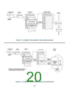
TABLE 31 illustrates a typical memory map for the ACE in the
Selective Message Monitor mode. This mode of operation
defines several fixed locations in the RAM. These locations allo-
cate in a manner that is compatible with the combined
RT/Selective Message Monitor mode. Refer to FIGURE 13 for an
example of a typical Selective Message Monitor Memory Map.
bit, and Subaddress, the Message Monitor eliminates the need
to determine the start and end of messages by software. The
development of such software tends to be a tedious task.
Moreover, at run time, it tends to entail a high degree of CPU
overhead.
23

 ETC [ ETC ]