TEA1716T
NXP Semiconductors
Resonant power supply control IC with PFC
7.8.3 HBC switch control
HBC switch control determines when the MOSFETs switch on and off. It uses the output
from several other blocks.
• A divider is used to realize alternate switching of the high- and low-side MOSFETs for
each oscillator cycle. The oscillator frequency is twice the half-bridge frequency.
• The controlled oscillator determines the switch-off point.
• Adaptive non-overlap time sensing determines the switch-on point. This is the
adaptive non-overlap time function.
• Several protection circuits and the state of the SSHBC/EN input determine whether
the resonant converter is allowed to start switching.
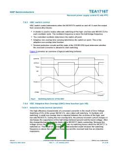
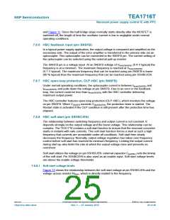
Figure 9 provides an overview of typical switching behavior.
GATEHS
GATELS
V
Boost
HB
0
0
I
Tr(HBC)
CFMIN
t
014aaa857
Fig 9. Switching behavior of the HBC
7.8.4 HBC Adaptive Non-Overlap (ANO) time function (pin HB)
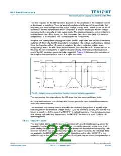
7.8.4.1 Inductive mode (normal operation)
The high efficiency characteristic of a resonant converter is the result of Zero-Voltage
Switching (ZVS) of the power MOSFETs, also called soft switching. To facilitate soft
switching, a small non-overlap time is required between the on-times of the high- and
low-side MOSFETs. During this non-overlap time, the primary resonant current charges or
discharges the capacitance of the half-bridge between ground and the boost voltage. After
this charge/discharge, the body diode of the MOSFET starts conducting. Because the
voltage across the MOSFET is zero, there are no switching losses when the MOSFET is
switched on. This mode of operation is called inductive mode because the switching
frequency is above the resonance frequency and the resonant tank has an inductive
impedance.
TEA1716T
All information provided in this document is subject to legal disclaimers.
© NXP B.V. 2012. All rights reserved.
Objective data sheet
Rev. 1 — 27 January 2012
21 of 46

 ETC [ ETC ]