TEA1716T
NXP Semiconductors
Resonant power supply control IC with PFC
t
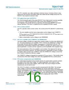
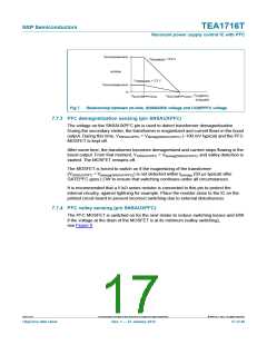
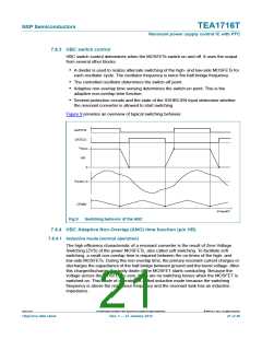
on(max)(lowmains)
on-time
V
= 0.9 V
SNSMAINS
V
= 3.3 V
SNSMAINS
t
on(max)(highmains)
0
V
V
V
COMPPFC
014aaa855
ton(COMPPFC)max
ton(COMPPFC)zero
Fig 7. Relationship between on-time, SNSMAINS voltage and COMPPFC voltage
7.7.3 PFC demagnetization sensing (pin SNSAUXPFC)
The voltage on the SNSAUXPFC pin is used to detect transformer demagnetization.
During the secondary stroke, the transformer is magnetized and current flows in the boost
output. During this time, VSNSAUXPFC < Vdemag(SNSAUXPFC) (100 mV typical) and the PFC
MOSFET is kept off.
After some time, the transformer becomes demagnetized and current stops flowing in the
boost output. From that moment, VSNSAUXPFC > Vdemag(SNSAUXPFC) and valley detection is
started. The MOSFET remains off.
The MOSFET is forced to switch on if the magnetizing of the transformer
(VSNSAUXPFC < Vdemag(SNSAUXPFC)) is not detected within tto(mag) (50 s typical) after
GATEPFC goes LOW to ensure that switching continues under all circumstances.
It is recommended that a 5 k series resistor is connected to this pin to protect the
internal circuitry, against lightning for example. Place the resistor close to the IC on the
printed circuit board to prevent incorrect switching due to external disturbances.
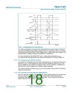
7.7.4 PFC valley sensing (pin SNSAUXPFC)
The PFC MOSFET is switched on for the next stroke to reduce switching losses and EMI
if the voltage at the drain of the MOSFET is at its minimum (valley switching),
see Figure 8.
TEA1716T
All information provided in this document is subject to legal disclaimers.
© NXP B.V. 2012. All rights reserved.
Objective data sheet
Rev. 1 — 27 January 2012
17 of 46

 ETC [ ETC ]