TEA1716T
NXP Semiconductors
Resonant power supply control IC with PFC
This is achieved by connecting a resistor Rss(PFC) and a capacitor Css(PFC) between
pin SNSCURPFC and the current sense resistor Rcur(PFC). At start-up, an internal current
source, Ich(ss)(PFC), charges the capacitor to VSNSCURPFC = Ich(ss)(PFC) Rss(PFC). The
voltage is limited to the maximum PFC soft start clamp voltage, Vclamp(ss)PFC. The
additional voltage across the charged capacitor results in a reduced peak current. After
start-up, the internal current source is switched-off, capacitor Css(PFC) discharges across
R
ss(PFC) and the peak current increases.
The start level and the time constant of the rising primary current can be adjusted
externally by changing the values of Rss(PFC) and Css(PFC)
.
V
– I
R
ssPFC
ocrPFC
chssPFC
---------------------------------------------------------------------------------------------
I
=
CurPFCpk
R
curPFC
= R
C
ssPFC
ssPFC
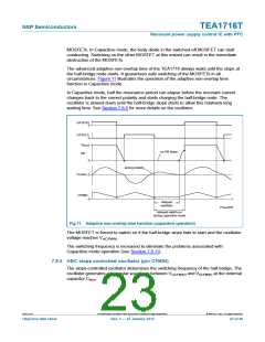
Soft stop is achieved by switching on the internal current source Ich(ss)(PFC). This current
charges Css(PFC). The increasing capacitor voltage reduces the peak current. The charge
current flows as long as the voltage on pin SNSCURPFC is below the maximum PFC soft
start voltage (0.5 V typical). If VSNSCURPFC exceeds the maximum PFC soft start voltage,
the soft start current source starts limiting the charge current. The voltage is only
measured during the off-time of the PFC power switch to determine accurately if the
capacitor is charged. The operation of the PFC is stopped when
V
SNSCURPFC > Vstop(ss)(PFC).
In the Burst stop state with the PFC not operating, pin SNSCURPFC is kept at the
maximum PFC soft start voltage. This allows an immediate start of the soft start sequence
when the PFC must operate after the Burst stop state.
7.7.7 PFC overcurrent regulation, OCR-PFC (pin SNSCURPFC)
The maximum peak current is limited cycle-by-cycle by sensing the voltage across an
external sense resistor (Rcur(PFC)) connected to the source of the external MOSFET. The
voltage is measured via the SNSCURPFC pin and is limited to Vocr(PFC)
.
A voltage peak appears on VSNSCURPFC when the PFC MOSFET is switched on due to the
discharging of the drain capacitance. The leading edge blanking time, tleb(PFC), ensures
that the overcurrent sensing block does not react to this transitory peak.
7.7.8 PFC mains undervoltage protection/brownout protection, UVP-mains
(pin SNSMAINS)
The voltage on the SNSMAINS pin is sensed continuously to prevent the PFC trying to
operate at very low mains input voltages. PFC switching stops as soon as VSNSMAINS
drops below Vuvp(SNSMAINS). Mains undervoltage protection is also called brownout
protection.
VSNSMAINS is clamped to a minimum value of Vpu(SNSMAINS) for fast restart as soon as the
mains input voltage recovers after a mains-dropout. The PFC (re)starts once VSNSMAINS
exceeds the start level Vstart(SNSMAINS)
.
TEA1716T
All information provided in this document is subject to legal disclaimers.
© NXP B.V. 2012. All rights reserved.
Objective data sheet
Rev. 1 — 27 January 2012
19 of 46

 ETC [ ETC ]