TEA1716T
NXP Semiconductors
Resonant power supply control IC with PFC
The time required for the HB transition depends on the amplitude of the resonant current
at the instant of switching. There is a complex relationship between this amplitude, the
frequency, the boost voltage and the output voltage. Ideally the IC switch on the MOSFET
as soon as the HB transition has been completed. If it waits any longer, the HP voltage
can swing back, especially at high output loads. The advanced adaptive non-overlap time
function takes care of this timing, so that choosing a fixed dead time (which is always a
compromise) is not required. This saves on external components.
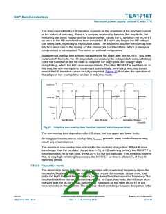
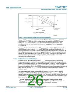
Adaptive non-overlap time sensing measures the HB slope after one MOSFET has been
switched off. Normally, the HB slope starts immediately (the voltage starts rising or falling).
Once the transition at the HB node is complete, the slope ends (the voltage stops
rising/falling), which the ANO time sensor detects. The other MOSFET is switched on. In
this way, the non-overlap time is optimized automatically, minimizing switching losses,
even if the HB transition cannot be fully completed. Figure 10 illustrates the operation of
the adaptive non-overlap time function in Inductive mode.
GATEHS
GATELS
V
Boost
HB
0
t
fast HB slope
slow HB slope
incomplete HB slope
014aaa858
Fig 10. Adaptive non-overlap time function (normal inductive operation)
The non-overlap time depends on the HB slope, but has upper and lower limits.
An integrated minimum non-overlap time, tno(min), prevents cross conduction occurring
under any circumstances.
The maximum non-overlap time is limited to the oscillator charge time. If the HB slope
lasts longer than the oscillator charge time (= 1⁄4 of HB switching period), the MOSFET is
forced to switch on. In this case, the MOSFET is not soft switching. This limitation ensures
that, at very high switching frequencies, the MOSFET on-time is at least 1⁄4 of the HB
switching period.
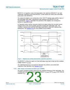
7.8.4.2 Capacitive mode
The description above holds for normal operation with a switching frequency above the
resonance frequency. When an error condition occurs (for example, output short, load
pulse too high) the switching frequency can be lower than the resonance frequency. The
resonant tank then has a capacitive impedance. In Capacitive mode, the HB slope does
not start after the MOSFET has switched off. Switching on the other MOSFET is not
recommended in this situation. The absence of soft switching increases dissipation in the
TEA1716T
All information provided in this document is subject to legal disclaimers.
© NXP B.V. 2012. All rights reserved.
Objective data sheet
Rev. 1 — 27 January 2012
22 of 46

 ETC [ ETC ]