TEA1716T
NXP Semiconductors
Resonant power supply control IC with PFC
MOSFETs. In Capacitive mode, the body diode in the switched-off MOSFET can start
conducting. Switching on the other MOSFET at this instant can result in the immediate
destruction of the MOSFETs.
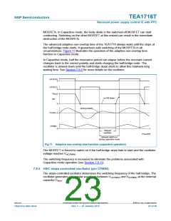
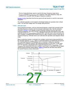
The advanced adaptive non-overlap time of the TEA1716 always waits until the slope at
the half-bridge node starts. It guarantees safe switching of the MOSFETs in all
circumstances. Figure 11 illustrates the operation of the adaptive non-overlap time
function in Capacitive mode.
In Capacitive mode, half the resonance period can elapse before the resonant current
changes back to the correct polarity and starts charging the half-bridge node. The
oscillator is slowed down until the half-bridge slope starts to allow this relatively long
waiting time. See Section 7.8.5 for more details on the oscillator.
GATEHS
0
GATELS
0
V
Boost
no HB slope
HB
0
0
wrong polarity
I
Tr(HBC)
CFMIN
0
t
delayed
oscillator
014aaa939
delayed switch-on
during capacitive mode
Fig 11. Adaptive non-overlap time function (capacitive operation)
The MOSFET is forced to switch on if the half-bridge slope fails to start and the oscillator
voltage reaches Vu(CFMIN)
.
The switching frequency is increased to eliminate the problems associated with
Capacitive mode operation (see Section 7.8.11).
7.8.5 HBC slope controlled oscillator (pin CFMIN)
The slope-controlled oscillator determines the switching frequency of the half-bridge. The
oscillator generates a triangular waveform between Vu(CFMIN) and Vl(CFMIN) at the external
capacitor Cfmin
.
TEA1716T
All information provided in this document is subject to legal disclaimers.
© NXP B.V. 2012. All rights reserved.
Objective data sheet
Rev. 1 — 27 January 2012
23 of 46

 ETC [ ETC ]