TEA1716T
NXP Semiconductors
Resonant power supply control IC with PFC
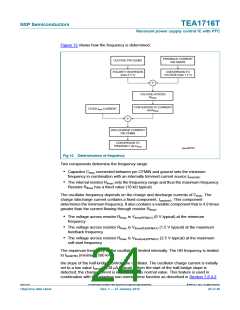
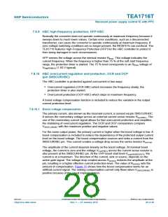
Figure 12 shows how the frequency is determined.
FEEDBACK CURRENT
PIN SNSFB
VOLTAGE PIN SSHBC
POLARITY INVERSION
(max 2.5 V)
CONVERSION TO
VOLTAGE (max 1.5 V)
VOLTAGE ACROSS
R
fmax
CONVERSION TO CURRENT
via R
FIXED f
CURRENT
min
fmax
(DIS-)CHARGE CURRENT
PIN CFMIN
CONVERSION TO
FRQUENCY via C
fmin
aaa-000767
Fig 12. Determination of frequency
Two components determine the frequency range:
• Capacitor Cfmin connected between pin CFMIN and ground sets the minimum
frequency in combination with an internally trimmed current source Iosc(min)
• The internal resistor Rfmax sets the frequency range and thus the maximum frequency.
Resistor Rfmax has a fixed value (18 k typical)
The oscillator frequency depends on the charge and discharge currents of Cfmin. The
charge /discharge current contains a fixed component, Iosc(min). This component
determines the minimum frequency. It also contains a variable component that is 4.9 times
greater than the current flowing through resistor Rfmax
:
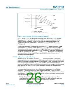
• The voltage across resistor Rfmax is Vfmin(RFMAX) (0 V typical) at the minimum
frequency
• The voltage across resistor Rfmax is Vfmax(fb)(RFMAX) (1.5 V typical) at the maximum
feedback frequency
• The voltage across resistor Rfmax is Vfmax(ss)(RFMAX) (2.5 V typical) at the maximum
soft start frequency
The maximum frequency of the oscillator is limited internally. The HB frequency is limited
to flimit(HB) (minimum 500 kHz).
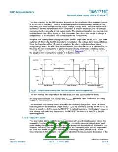
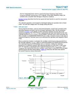
the slope of the half-bridge controls the oscillator. The oscillator charge current is initially
set to a low value Iosc(red) (30 A typical). When the start of the half-bridge slope is
detected, the charge current is increased to its normal value. This feature is used in
combination with the adaptive non-overlap time function as described in Section 7.8.4.2
TEA1716T
All information provided in this document is subject to legal disclaimers.
© NXP B.V. 2012. All rights reserved.
Objective data sheet
Rev. 1 — 27 January 2012
24 of 46

 ETC [ ETC ]