EAGLE
PRELIMINARY
Ver 1.3
3.5.2 Interrupt Vector Register (INTVEC)
An 8-bit interrupt vector is generated by combining the upper 3-bit programmable interrupt vector with the lower 5 bits
of priority encoding data as shown in the table below.
Address : FFE0 0C04h
Bit
31 : 8
7 : 5
4 : 0
R/W
R
R/W
R
Description
Default Value
Reserved.
-
Interrupt Vector Higher 3 Bit. Programmable Bits.
Interrupt Vector Lower 5 Bit. Priority Encoding Data
001b
00h
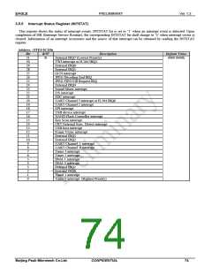
3.5.3 Interrupt Vector Clear Register (INTVECCLR)
Upon exit from Interrupt Service Routine after an interrupt service completes, the interrupt controller clears the interrupt bit
by writing the interrupt code to INTVECCLR register.
Address : FFE0 0C08h
Bit
31 : 5
4 : 0
R/W
R
W
Description
Default Value
Reserved.
Interrupt Clear Vector Value.
-
00h
It is possible to clear the internal interrupt bit by writing the code value of
the corresponding interrupt after the completion of the Interrupt Service
Routine according to the interrupt priority.
Vector No.
Description
Remark
Interrupt is generated
sequentially according to
priority.
31
30
29
28
27
26
25
24
23
22
21
20
19
18
17
16
15
14
13
12
11
10
9
External IRQ7 (Lowest Priority)
TWI interrupt or H.264 IRQ1
External IRQ6
External IRQ5
GUN interrupt
JPEG Decoding End IRQ
JPEG FIFO Fill Request IRQ
External IRQ4
Sound Mixer interrupt
I2S interrupt
SDC interrupt
UART Channel 3 interrupt or H.264 IRQ0
UART Channel 2 interrupt
SPI interrupt
USB device interrupt
NAND Flash Controller interrupt
Key Scan interrupt
CRT External Sync. Detect interrupt
USB host interrupt
Frame Vsync interrupt
External IRQ3
External IRQ2
UART Channel 1 interrupt
UART Channel 0 interrupt
Timer 3 interrupt
8
7
6
Timer 2 interrupt
5
DMA 1 interrupt
4
DMA 0 interrupt
3
External IRQ1
2
External IRQ0
1
Timer 1 interrupt
0
Timer 0 interrupt (Highest Priority)
Table 3-9 Interrupt Vector & Priority
Beijing Peak Microtech Co.Ltd.
CONFIDENTIAL
72

 ETC [ ETC ]