EAGLE
PRELIMINARY
Ver 1.3
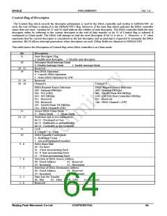
DMA Register Summary
Address
Register Name
Description
FFE0 0800h DMA status register(GDMASTAT)
FFE0 0804h DMA interrupt mask register(GDMAIM)
FFE0 0808h DMA enable status register(GDMAESTAT)
FFE0 080Ch DMA request status & synchronization register (GDMARSS)
FFE0 0810h DMA configuration register(GDMACFG)
Error and termination interrupt status
Control on interrupt inactivation
Channel status
DMA request status and sync control
DMA configuration control
Last request control
FFE0 0818h DMA last request register(GDMALR)
FFE0 0820h DMA Ch.0 Control Register(GDMACON0)
FFE0 0824h DMA Ch.0 Source Address Register(GDMAS0)
FFE0 0828h DMA Ch.0 Destination Address Register(GDMAD0)
FFE0 082Ch DMA Ch.0 Transfer Count Register(GDMAT0)
FFE0 0830h DMA Ch.0 Descriptor Table Address Register(GDMADT0)
FFE0 0840h DMA Ch.1 Control Register(GDMACON1)
FFE0 0844h DMA Ch.1 Source Address Register(GDMAS1)
FFE0 0848h DMA Ch.1 Destination Address Register(GDMAD1)
FFE0 084Ch DMA Ch.1 Transfer Count Register(GDMAT1)
FFE0 0850h DMA Ch.1 Descriptor Table Address Register(GDMADT1)
Control bit
Read address for data transfer
Write address for data transfer
Number for data transfer
Descriptor address
Channel control
Read address for data transfer
Write address for data transfer
Data transfer count
Descriptor address
Table 3-6 DMA Registers Table
DMA Operation
The DMA controller can receive five individual DMA requests. DMA operation shall response to a selected request.
In order for the DMA controller to perform a configured DMA operation, the Run DMA Operation bit in GDMACON
should be changed to Starts DMA Operation by S/W. Upon completion, the DMA controller automatically clears the run bit.
A DMA request signal to DMA controller can be generated by software program or by other peripheral modules. The DMA
controller is only aware of a DMA request if the request signal is asserted through an external pin or through other module as
determined by Request Source Selection in GDMACON and a request source can generate multiple requests until the
corresponding source selection is disabled. In fact, the DMA channel n (SW) is allocated as a request source regardless of the
external pin or peripherals. For example, it can be selected as a request source for simple memory transfer, such as the data
transfer from xxxxxxxxh to yyyyyyyyh in memory location.
The DMA controller has two modes : Direct mode and Chain mode. In Direct mode, user can write directly to configure
GDMAS, GDMAD and GDMAT. The DMA operation starts when the DMA Run bit and Direct bit in GDMACON are set.
To enable burst operation in Chain mode, user must program the defined descriptor address in GDMADT. DMA operation
starts after run DMA operation bit and chain-mode bit in GDMACON are configured,
The DMA controller generates three types of addresses for Source and Destination address. When fixed address is used, the
DMA controller enables the address output fixed by GDMAS and GDMAD. In increment address, the DMA controller
increments the address in GDMAS and GDMAD for every data transfer. In decrement address, DMA controller decrements
the address of GDMAS and GDMAD for every data transfer. If an 8-bit data size transfer occurs,, the address in GDMAS
and GDMAD are computed as current address value plus 0, +1 or -1. If a 16-bit data size transfer occurs, 0, +2 or -2 will be
added to the current address in GDMAS and GDMAD. For 32-bit transfer, the current Source and Destination address is
added with a constant value of 0, +4 or –4.
Beijing Peak Microtech Co.Ltd.
CONFIDENTIAL
60

 ETC [ ETC ]