EAGLE
PRELIMINARY
Ver 1.3
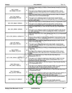
Digital Red Output Data[0] or GUN[0] or External Interrupt Source[0] or I2S Serial
Data Output
R[0] / GUN[0] /
EXT_IRQ[0] / I2S_SDO
B
This signal can be configured as digital red output data[0], GUN[0], external
interrupt source[0] or serial output data of I2S, as determined by pin mux control
register.
Digital Red Output Data[1] or External Interrupt Source[4] or DMA Ch.0 Request
Strobe (Active Low) or I2S Serial Data Input
R[1] / EXT_IRQ[4] /
DMA_REQx[0] / I2S_SDI
B
B
B
This signal can be configured as digital red output data[1], external interrupt
source[4], request strobe of DMA Ch.0 or serial input data of I2S, as determined by
pin mux control register.
Digital Red Output Data[2] or External Interrupt Source[5] or Programmable I/O[45]
R[2] / EXT_IRQ[5] / GPIO[45]
R[3] / DEC_DIN[0] / GPIO[46]
This signal can be configured as digital red output data[2], external interrupt
source[5] or programmable I/O[45], as determined by pin mux control register.
Digital Red Output Data[3] or
I/O[46]
or Programmable
Video Decoder Data Bus [0]
This signal can be configured as digital red output data[3], data[0] of video decoder
for image capturing in YCbCr format or programmable I/O[46], as determined by
pin mux control register.
Digital Red Output Data [7:4] or
I/O[50:47]
or Programmable
Video Decoder Data Bus [4:1]
R[7:4] / DEC_DIN[4:1] / GPIO[50:47]
B
B
B
B
B
B
B
Indicates either as digital red output data[7:4], data[4:1] of video decoder for image
capturing in YCbCr format or programmable I/O[50:47], as determined by pin mux
control register.
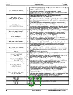
Digital Green Output Data[0] or External Interrupt Source[1] or UART Ch.3 Rx
Data or I2S Serial Bit Clock
G[0] / EXT_IRQ[1] /
UART_Rx[3] / I2S_SCK
This signal can be configured as digital green output data[0], external interrupt
source[1], receive data of UART Ch.3 or serial clock of I2S, as determined by pin
mux control register.
Digital Green Output Data [1] or GUN
/ Right Clock
or External Interrupt Source[6] or I2S Left
[1]
G[1] / GUN[1] /
EXT_IRQ[6] / I2S_LRCK
This signal can be configured as digital green output data[1], GUN[1], external
interrupt source[6] or left or right clock of I2S, as determined by pin mux control
register.
Digital Green Output Data [3:2] or
Programmable I/O[54:53]
or
Video Decoder Data Bus[6:5]
G[3:2] / DEC_DIN[6:5] / GPIO[54:53]
This signal can be configured as digital green output data[3:2], data[6:5] of video
decoder for image capturing in YCbCr format or programmable I/O[54:53], as
determined by pin mux control register.
Digital Green Output Data[4] or USB Over-Current or
Video Decoder Data Bus
or Programmable I/O[55]
[7]
G[4] / USB_ovrcur /
DEC_DIN[7] / GPIO[55]
This signal can be configured as digital green output data[4], over current indicator of
USB, data[7] of video decoder for image capturing in YCbCr format or
programmable I/O[55], as determined by pin mux control register.
Digital Green Output Data[5] or USB Port Power or
or Programmable I/O[56]
Video Decoder Data Active
G[5] / USB_prtpwr /
DEC_ACTIVE / GPIO[56]
This signal can be configured as digital green output data[5], port power indicator of
USB, data active of video decoder for image capturing in YCbCr format or
programmable I/O[56], as determined by pin mux control register.
Digital Green Output Data [6] or
Video Decoder Horizontal Synchronization
or Programmable I/O[57]
Input signal
G[6] / HSYNC_IN / GPIO[57]
This signal can be configured as digital green output data[6], horizontal
synchronization signal of video decoder or programmable I/O[57], as determined by
pin mux control register.
Beijing Peak Microtech Co.Ltd.
CONFIDENTIAL
30

 ETC [ ETC ]