LHF80V25
11
sharp
(7)
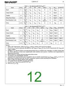
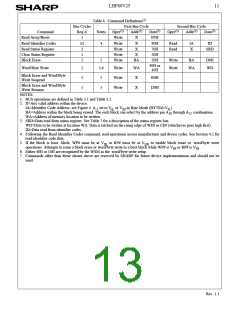
Table 4. Command Definitions
Bus Cycles
First Bus Cycle
Second Bus Cycle
(1)
(2)
(3)
(1)
(2)
(3)
Command
Read Array/Reset
Read Identifier Codes
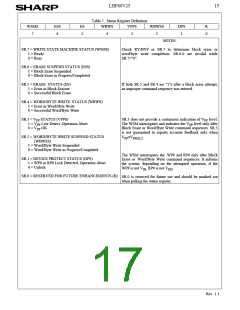
Read Status Register
Clear Status Register
Block Erase
Req’d.
Notes
4
Oper
Addr
Data
Oper
Addr
Data
1
≥2
2
Write
Write
Write
Write
Write
X
X
FFH
90H
70H
50H
20H
Read
Read
IA
X
ID
X
SRD
1
X
2
5
BA
Write
Write
BA
D0H
WD
40H or
10H
Word/Byte Write
2
1
1
5,6
Write
Write
Write
WA
X
WA
Block Erase and Word/Byte
Write Suspend
5
5
B0H
D0H
Block Erase and Word/Byte
Write Resume
X
NOTES:
1. BUS operations are defined in Table 3.1 and Table 3.2.
2. X=Any valid address within the device.
IA=Identifier Code Address: see Figure 4. A set to V or V in Byte Mode (BYTE#=V ).
-1
IL
IH
IL
BA=Address within the block being erased. The each block can select by the address pin A through A combination.
18
12
WA=Address of memory location to be written.
3. SRD=Data read from status register. See Table 7 for a description of the status register bits.
WD=Data to be written at location WA. Data is latched on the rising edge of WE# or CE# (whichever goes high first).
ID=Data read from identifier codes.
4. Following the Read Identifier Codes command, read operations access manufacturer and device codes. See Section 4.2 for
read identifier code data.
5. If the block is boot block, WP# must be at V or RP# must be at V
operations. Attempts to issue a block erase or word/byte write to a boot block while WP# is V or RP# is V .
6. Either 40H or 10H are recognized by the WSM as the word/byte write setup.
to enable block erase or word/byte write
IH
HH
IH
IH
7. Commands other than those shown above are reserved by SHARP for future device implementations and should not be
used.
Rev. 1.1

 ETC [ ETC ]