LHF80V25
14
sharp
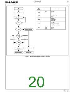
4.8 Word/Byte Write Suspend Command
4.10 Block Locking
The Word/Byte Write Suspend command allows
word/byte write interruption to read data in other flash
memory locations. Once the word/byte write process
starts, writing the Word/Byte Write Suspend command
requests that the WSM suspend the word/byte write
sequence at a predetermined point in the algorithm. The
device continues to output status register data when read
after the Word/Byte Write Suspend command is written.
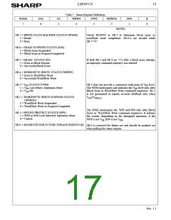
Polling status register bits SR.7 and SR.2 can determine
when the word/byte write operation has been suspended
(both will be set to "1"). RY/BY# will also transition to
This Boot Block Flash memory architecture features two
hardware-lockable boot blocks so that the kernel code for
the system can be kept secure while other blocks are
programmed or erased as necessary.
4.10.1 V =V for Complete Protection
PP
IL
The V
programming voltage can be held low for
PP
complete write protection of all blocks in the flash device.
4.10.2 WP#=V for Block Locking
IL
High Z. Specification t
suspend latency.
defines the word/byte write
WHRZ1
The lockable blocks are locked when WP#=V ; any
IL
program or erase operation to a locked block will result in
an error, which will be reflected in the status register. For
top configuration, the top two boot blocks are lockable.
For the bottom configuration, the bottom tow boot blocks
are lockable. Unlocked blocks can be programmed or
At this point, a Read Array command can be written to
read data from locations other than that which is
suspended. The only other valid commands while
word/byte write is suspended are Read Status Register and
Word/Byte Write Resume. After Word/Byte Write
Resume command is written to the flash memory, the
WSM will continue the word/byte write process. Status
register bits SR.2 and SR.7 will automatically clear and
erased normally (Unless V is below V
).
PP
PPLK
4.10.3 WP#=V for Block Unlocking
IH
RY/BY# will return to V . After the Word/Byte Write
Resume command is written, the device automatically
OL
WP#=V unlocks all lockable blocks.
IH
outputs status register data when read (see Figure 8). V
PP
These blocks can now be programmed or erased.
must remain at V
(the same V level used for
PPH1/2
PP
word/byte write) while in word/byte write suspend mode.
RP# must also remain at V or V (the same RP# level
WP# controls 2 boot blocks locking and V provides
protection against spurious writes. Table 6 defines the
write protection methods.
PP
IH
HH
used for word/byte write). WP# must also remain at V or
IL
V
(the same WP# level used for word/byte write).
IH
4.9 Considerations of Suspend
After the suspend command write to the CUI, read status
register command has to write to CUI, then status register
bit SR.6 or SR.2 should be checked for places the device
in suspend mode.
Table 6. Write Protection Alternatives
Operation
V
RP#
X
WP#
X
Effect
PP
V
All Blocks Locked.
All Blocks Locked.
All Blocks Unlocked.
2 Boot Blocks Locked.
All Blocks Unlocked.
IL
Block Erase
or
V
X
IL
>V
V
X
PPLK
HH
Word/Byte Write
V
V
IH
IL
V
IH
Rev. 1.1

 ETC [ ETC ]