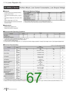
1-1-4 Linear Regulator ICs
Application Note
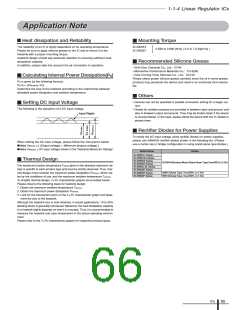
■ Heat dissipation and Reliability
Mounting Torque
■
The reliability of an IC is highly dependent on its operating temperature.
Please be sure to apply silicone grease to the IC and to mount it to the
heatsink with a proper mounting torque.
SI-3000KF
SI-3000ZF
0.588 to 0.686 [N•m] ( 6.0 to 7.0 [kgf•cm] )
Heatsink design should pay particular attention to ensuring sufficient heat
dissipation capacity.
Recommended Silicone Grease
• Shin-Etsu Chemical Co., Ltd.: G746
■
In addition, please take into account the air convection in operation.
• Momentive Performance Materials Inc.: YG-6260
• Dow Corning Toray Silicones Co., Ltd.: SC102
Please select proper silicone grease carefully since the oil in some grease
products may penetrate the device and result in an extremely short device
life.
)
Calculating Internal Power Dissipation(
PD
PD is given by the following formula:
PD=IO • [VIN(mean)–VO]
Determine the size of the heatsink according to the relationship between
allowable power dissipation and ambient temperature.
■
Others
■
• Devices can not be operated in parallel connection aiming for a larger cur-
rent.
Setting DC Input Voltage
The following is the waveform of a DC input voltage.
■
• Diodes for isolation purpose are provided in between input and ground, and
also in between output and ground. They may be broken down if the device
is reverse biased. In this case, please clamp the device with low VF diodes to
protect them.
Input Ripple
Rectifier Diodes for Power Supplies
■
To rectify the AC input voltage using rectifier diodes for power supplies,
please use SANKEN rectifier diodes shown in the following list. (Please
use a center-tap or bridge configuration in using stand-alone type diodes.)
When setting the DC input voltage, please follow the instructions below:
●Make VIN(min) ≥ [ (Output voltage) + (Minimum dropout voltage) ]
●Make VIN(max) ≤ DC input voltage shown in the "Absolute Maximum Ratings"
Series Name
Diodes
SI-3000LU Series
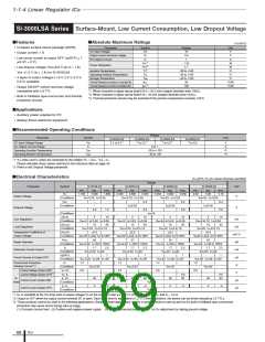
SI-3000LSA Series
SI-3000KS Series
SI-3000KD Series
SI-3000LLSL Series
SI-3000ZD Series
SI-3000KF Series
SI-3000ZF Series
Thermal Design
■
SJPM-H4(Surface-Mount Stand-Alone Type,VRM:400V,IO:2.0A)
The maximum junction temperature Tj(max) given in the absolute maximum rat-
ings is specific to each product type and must be strictly observed. Thus, ther-
mal design must consider the maximum power dissipation PD(max), which var-
ies by the conditions of use, and the maximum ambient temperature Ta(max).
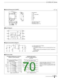
To simplify thermal design, Ta-PD characteristic graphs are provided herein.
Please observe the following steps for heatsink design:
AM01Z(Axial Type, VRM:200V, IO:1.0A)
RM10Z(Axial Type, VRM:200V, IO:1.5A)
1. Obtain the maximum ambient temperature Ta(max).
2. Obtain the maximum power dissipation PD(max).
3. Look for the intersection point on the Ta-PD characteristic graph and deter-
mine the size of the heatsink.
Although the heatsink size is now obtained, in actual applications, 10-to-20%
derating factor is generally introduced. Moreover, the heat dissipation capacity
of a heatsink highly depends on how it is mounted. Thus, it is recommended to
measure the heatsink and case temperature in the actual operating environ-
ment.
Please refer to the Ta-PD characteristic graphs for respective product types.
ICs
65

 ETC [ ETC ]