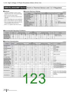
1-2-6 High Voltage 3-Phase Brushless Motor Driver ICs
SMA6860M Series
Built-in Overcurrent Protection, Thermal Shutdown, and Overcurrent Limiting Circuits
■Features
• Built-in boot diode with 210-
■Absolute Maximum Ratings
(Ta=25°C)
Conditions
Ω limiting resistor
Ratings
SMA6863M
500
20
20
2.5
3.75
Parameter
Symbol
Unit
SMA6862M
SMA6865M
• Built-in overcurrent protection circuit (OCP)
MOSFET Output Breakdown Voltage VDSS
V
V
V
A
A
V
CC=15V, I
Between VCC and COM
Between V and HS (U, V, W)
D=100uA, VIN=0V
• Overcurrent protection with off-time period
adjustable by an external capacitor
Control Supply Voltage (VCC
)
VCC
VBS
Io
Control Supply Voltage (Bootstrap)
Output Current (continuous)
Output Current (pulse)
Input Voltage
B
1.5
2.25
2.5
3.75
• Overcurrent limiting operation
Iop
PW≤100µs, duty=1%
HIN1 to HIN3, LIN1 to LIN3
TC=25℃
All elements operating
All elements operating
VIN
PD
θj-c
θj-a
Tc
–0.5 to +7
V
W
• Built-in thermal shutdown (TSD) circuit
• Externally controllable shutdown operation
Power Dissipation
28
4.46
31.25
Thermal Resistance (Junction to Case)
Thermal Resistance (Junction to Ambient Air)
Operating Case Temperature
Junction Temperature (Power part)
℃/W
℃/W
℃
℃
℃
–20 to +100
150
Tj
Storage Temperature Tstg
–40 to +150
■Recommended Operating Conditions
Ratings
Parameter
Symbol
SMA6862M
SMA6863M
SMA6865M
Unit
Conditions
min.
-
13.5
1.5
0.5
-
typ.
300
-
-
-
max.
400
16.5
-
-
125
min.
-
13.5
1.5
0.5
-
typ.
300
-
-
-
max.
400
16.5
-
-
125
min.
-
13.5
1.5
0.5
-
typ.
300
-
-
-
max.
400
16.5
-
-
125
Main Supply Voltage
Control Supply Voltage
Input Signal Dead Time
Minimum Input Pulse Width
Junction Temperature
VBB
VCC
tdead
Tw
V
V
Between VBB and LS
Between VCC and COM
µ
µ
s
s
Tj=–20℃ to +150℃
Tj
-
-
-
℃
■Electrical Characteristics
(Ta=25°C)
Ratings
SMA6863M
typ.
4.2
Parameter
Symbol
SMA6862M
SMA6865M
typ.
4.2
Unit
Conditions
min.
-
-
typ.
4.2
135
2.9
2.1
10.0
10.5
0.5
11.0
11.5
0.5
135
115
20
1.0
0.53
2
-
1.0
70
max.
min.
-
-
max.
7
380
3.4
-
11.0
11.5
-
12.0
12.5
-
150
130
-
1.1
0.5565
-
min.
-
-
max.
7
380
3.4
-
11.0
11.5
-
12.0
12.5
-
150
130
-
1.1
0.5565
-
10
1.3
-
Control Supply Current
Boot Supply Current
Icc
7
380
3.4
-
11.0
11.5
-
12.0
12.5
-
150
130
-
1.1
0.5565
-
10
1.3
-
mA
uA
V
V
cc=15V
B=15V, HIN=5V,
I
B
135
2.9
2.1
10.0
10.5
0.5
11.0
11.5
0.5
135
115
20
1.0
0.53
2
135
2.9
2.1
10.0
10.5
0.5
11.0
11.5
0.5
135
115
20
1.0
0.53
2
VIH
-
-
-
Input Voltage
V
VCC=15V
V
IL
1.6
9.0
9.5
-
10.0
10.5
-
120
100
-
0.9
0.5035
-
-
-
-
-
500
-
1.6
9.0
9.5
-
10.0
10.5
-
120
100
-
0.9
0.5035
-
-
-
-
-
500
-
1.6
9.0
9.5
-
10.0
10.5
-
120
100
-
0.9
0.5035
-
-
-
UVHL
UVHH
UVhys
UVLL
UVLH
UVhys
Between V
B and U (V, W)
Undervoltage Lock Out
V
Hysteresis
Between VCC and COM
Hysteresis
Undervoltage Lock Out
V
T
DH
DL
DHYS
TRIP
Termal Protection and
Release Threshold
T
T
V
℃
VCC=15V
Overcurrent Protection Trip Voltage
Current Limiting Reference Voltage
Overcurrent Protection Retention Time
Boot Diode Leakage Current
Boot Diode Forward Voltage
Boot Diode Reverse Recovery Time
Boot Diode Series Resistance
MOSFET Output Breakdown Voltage
MOSFET Output Leakage Current
V
V
ms
µA
V
ns
Ω
V
V
V
V
V
CC=15V
V
LIM
CC=15V
tp
RC=5V, RR=360kΩ, CC=0.0047µF
R=500V
ILBD
-
1.0
70
210
-
10
1.3
-
-
-
-
0.8
70
210
-
V
FBD
IF
=0.05A
Trrb
Rb
-
-
500
-
IF
/IRP=100mA/100mA
210
-
-
-
-
100
-
-
100
V
DSS
V
V
V
CC=15V, I
CC=15V, VDS=500V, VIN=0V
CC=15V, I =1.25A
D=100uA, VIN=0V
I
DSS
-
100
-
µA
D
MOSFET DC ON Resistance
MOSFET Diode Forward Voltage
R
DS(ON)
-
3.6
4.0
-
2.0
2.4
-
1.4
1.7
Ω
(0.75A for the SMA6862M), VIN=5V
CC=15V, I =1.25A
(0.75A for the SMA6862M), VIN=0V
V
D
V
SD
-
1.0
1.5
-
1.0
1.5
-
1.0
1.5
V
td(on)
tr
-
-
-
-
-
-
-
-
-
-
720
40
110
670
20
600
40
120
555
20
-
-
-
-
-
-
-
-
-
-
-
-
-
-
-
-
-
-
-
-
790
60
115
725
20
680
70
120
605
20
-
-
-
-
-
-
-
-
-
-
-
-
-
-
-
-
-
-
-
-
750
60
100
680
20
640
65
100
560
20
-
-
-
-
-
-
-
-
-
-
High Side Switching Time trr
td(off)
ns
ns
V
BB=300V, VCC=15V, I
(2.5A for the SMA6863M and SMA6865M),
IN=0 to 5V
Inductive load
D=1.5A
tf
td(on)
tr
V
Low Side Switching Time trr
td(off)
tf
ICs
126

 ETC [ ETC ]