ST90158 - RESET AND CLOCK CONTROL UNIT (RCCU)
OSCILLATOR CHARACTERISTICS (Cont’d)
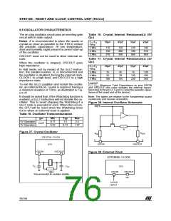
CERAMIC RESONATORS
Murata Electronics CERALOCK resonators have been tested with the ST90158 at 3, 3.68, 4 and 5 MHz.
Some resonators have built-in capacitors (see Table 18).
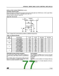
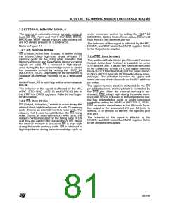
The test circuit is shown in Figure 40.
Figure 40. Test circuit
ST90158
OSCOUT
V
DD
V
OSCIN
SS
Rp
Rd
CERALOCK
C1 C2
V1
V2
Table 18 shows the recommended conditions at different frequencies.
Table 18. Obtained Results
Freq.
Parts Number
C1 (PF)
C2 (PF)
Rp (Ohm)
Rd (Ohm)
(MHz)
CSA3.00MG
CST3.00MGW
CSA3.68MG
30
(30)
30
30
(30)
30
Open
Open
Open
Open
Open
Open
Open
Open
Open
Open
Open
0
0
0
0
0
0
0
0
0
0
0
3
3.68
4
CST3.68MGW
CSTCC3.68MG
CSA4.00MG
(30)
(15)
30
(30)
(15)
30
CST4.00MGW
CSTCC4.00MG
CSA5.00MG
(30)
(15)
30
(30)
(15)
30
5
CST5.00MGW
CSTCC5.00MG
(30)
(15)
(30)
(15)
Advantages of using ceramic resonators:
Test conditions:
CST and CSTCC types have built-in loading ca-
pacitors (those with values shown in parentheses
()).
The evaluation conditions are 2.7 to 5.5 V for the
supply voltage and -40° to 85° C for the tempera-
ture range.
Rp is always open in the previous table because
there is no need for a parallel resistor with a reso-
nator (it is needed only with a crystal).
Caution:
The above circuit condition is for design reference
only.
Recommended C1, C2 value depends on the cir-
cuit board used.
77/199
9

 ETC [ ETC ]