ST72104G, ST72215G, ST72216G, ST72254G
2
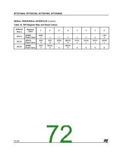
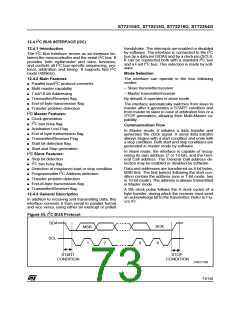
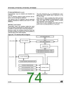
I C BUS INTERFACE (Cont’d)
How to release the SDA / SCL lines
After completion of this transfer (and acknowledge
from the slave if the ACK bit is set):
Set and subsequently clear the STOP bit while
BTF is set. The SDA/SCL lines are released after
the transfer of the current byte.
– The EVF bit is set by hardware with interrupt
generation if the ITE bit is set.
12.4.4.2 Master Mode
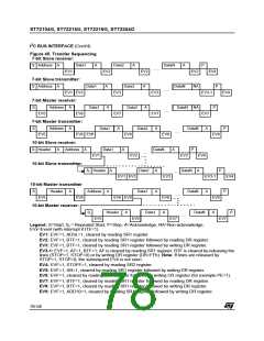
Then the master waits for a read of the SR1 regis-
ter followed by a write in the CR register (for exam-
ple set PE bit), holding the SCL line low (see Fig-
ure 45 Transfer sequencing EV6).
To switch from default Slave mode to Master
mode a Start condition generation is needed.
Start condition
Next the master must enter Receiver or Transmit-
ter mode.
Setting the START bit while the BUSY bit is
cleared causes the interface to switch to Master
mode (M/SL bit set) and generates a Start condi-
tion.
Note: In 10-bit addressing mode, to switch the
master to Receiver mode, software must generate
a repeated Start condition and resend the header
sequence with the least significant bit set
(11110xx1).
Once the Start condition is sent:
– The EVF and SB bits are set by hardware with
an interrupt if the ITE bit is set.
Then the master waits for a read of the SR1 regis-
ter followed by a write in the DR register with the
Slave address, holding the SCL line low (see
Figure 45 Transfer sequencing EV5).
Master Receiver
Following the address transmission and after SR1
and CR registers have been accessed, the master
receives bytes from the SDA line into the DR reg-
ister via the internal shift register. After each byte
the interface generates in sequence:
Slave address transmission
– Acknowledge pulse if if the ACK bit is set
Then the slave address is sent to the SDA line via
the internal shift register.
– EVF and BTF bits are set by hardware with an in-
terrupt if the ITE bit is set.
In 7-bit addressing mode, one address byte is
sent.
Then the interface waits for a read of the SR1 reg-
ister followed by a read of the DR register, holding
the SCL line low (see Figure 45 Transfer se-
quencing EV7).
In 10-bit addressing mode, sending the first byte
including the header sequence causes the follow-
ing event:
– The EVF bit is set by hardware with interrupt
generation if the ITE bit is set.
To close the communication: before reading the
last byte from the DR register, set the STOP bit to
generate the Stop condition. The interface goes
automatically back to slave mode (M/SL bit
cleared).
Then the master waits for a read of the SR1 regis-
ter followed by a write in the DR register, holding
the SCL line low (see Figure 45 Transfer se-
quencing EV9).
Then the second address byte is sent by the inter-
face.
Note: In order to generate the non-acknowledge
pulse after the last received data byte, the ACK bit
must be cleared just before reading the second
last data byte.
76/140

 ETC [ ETC ]