ST72104G, ST72215G, ST72216G, ST72254G
2
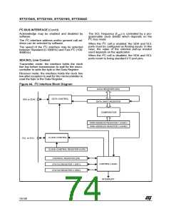
12.4 I C BUS INTERFACE (I2C)
12.4.1 Introduction
handshake. The interrupts are enabled or disabled
by software. The interface is connected to the I C
2
2
The I C Bus Interface serves as an interface be-
2
bus by a data pin (SDAI) and by a clock pin (SCLI).
tween the microcontroller and the serial I C bus. It
2
It can be connected both with a standard I C bus
provides both multimaster and slave functions,
2
2
and a Fast I C bus. This selection is made by soft-
and controls all I C bus-specific sequencing, pro-
2
ware.
tocol, arbitration and timing. It supports fast I C
mode (400kHz).
Mode Selection
12.4.2 Main Features
The interface can operate in the four following
modes:
2
■ Parallel-bus/I C protocol converter
– Slave transmitter/receiver
■ Multi-master capability
– Master transmitter/receiver
By default, it operates in slave mode.
■ 7-bit/10-bit Addressing
■ Transmitter/Receiver flag
■ End-of-byte transmission flag
■ Transfer problem detection
The interface automatically switches from slave to
master after it generates a START condition and
from master to slave in case of arbitration loss or a
STOP generation, allowing then Multi-Master ca-
pability.
2
I C Master Features:
■ Clock generation
2
■ I C bus busy flag
Communication Flow
■ Arbitration Lost Flag
In Master mode, it initiates a data transfer and
generates the clock signal. A serial data transfer
always begins with a start condition and ends with
a stop condition. Both start and stop conditions are
generated in master mode by software.
■ End of byte transmission flag
■ Transmitter/Receiver Flag
■ Start bit detection flag
■ Start and Stop generation
In Slave mode, the interface is capable of recog-
nising its own address (7 or 10-bit), and the Gen-
eral Call address. The General Call address de-
tection may be enabled or disabled by software.
2
I C Slave Features:
■ Stop bit detection
2
■ I C bus busy flag
Data and addresses are transferred as 8-bit bytes,
MSB first. The first byte(s) following the start con-
dition contain the address (one in 7-bit mode, two
in 10-bit mode). The address is always transmitted
in Master mode.
■ Detection of misplaced start or stop condition
2
■ Programmable I C Address detection
■ Transfer problem detection
■ End-of-byte transmission flag
■ Transmitter/Receiver flag
12.4.3 General Description
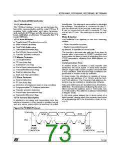
A 9th clock pulse follows the 8 clock cycles of a
byte transfer, during which the receiver must send
an acknowledge bit to the transmitter. Refer to Fig-
ure 43.
In addition to receiving and transmitting data, this
interface converts it from serial to parallel format
and vice versa, using either an interrupt or polled
2
Figure 43. I C BUS Protocol
SDA
MSB
ACK
SCL
1
2
8
9
START
STOP
CONDITION
CONDITION
VR02119B
73/140

 ETC [ ETC ]