ST72104G, ST72215G, ST72216G, ST72254G
2
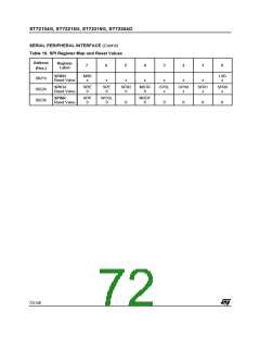
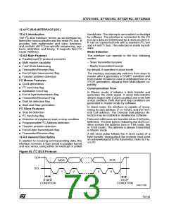
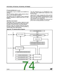
I C BUS INTERFACE (Cont’d)
12.4.4 Functional Description
– EVF and BTF bits are set with an interrupt if the
ITE bit is set.
Refer to the CR, SR1 and SR2 registers in Section
12.4.7. for the bit definitions.
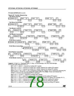
Then the interface waits for a read of the SR1 reg-
ister followed by a read of the DR register, holding
the SCL line low (see Figure 45 Transfer se-
quencing EV2).
2
By default the I C interface operates in Slave
mode (M/SL bit is cleared) except when it initiates
a transmit or receive sequence.
First the interface frequency must be configured
using the FRi bits in the OAR2 register.
Slave Transmitter
Following the address reception and after SR1
register has been read, the slave sends bytes from
the DR register to the SDA line via the internal shift
register.
12.4.4.1 Slave Mode
As soon as a start condition is detected, the
address is received from the SDA line and sent to
the shift register; then it is compared with the
address of the interface or the General Call
address (if selected by software).
The slave waits for a read of the SR1 register fol-
lowed by a write in the DR register, holding the
SCL line low (see Figure 45 Transfer sequencing
EV3).
Note: In 10-bit addressing mode, the comparision
includes the header sequence (11110xx0) and the
two most significant bits of the address.
When the acknowledge pulse is received:
Header matched (10-bit mode only): the interface
generates an acknowledge pulse if the ACK bit is
set.
– The EVF and BTF bits are set by hardware with
an interrupt if the ITE bit is set.
Address not matched: the interface ignores it
and waits for another Start condition.
Closing slave communication
After the last data byte is transferred a Stop Con-
dition is generated by the master. The interface
detects this condition and sets:
Address matched: the interface generates in se-
quence:
– Acknowledge pulse if the ACK bit is set.
– EVF and STOPF bits with an interrupt if the ITE
bit is set.
– EVF and ADSL bits are set with an interrupt if the
ITE bit is set.
Then the interface waits for a read of the SR2 reg-
ister (see Figure 45 Transfer sequencing EV4).
Then the interface waits for a read of the SR1 reg-
ister, holding the SCL line low (see Figure 45
Transfer sequencing EV1).
Next, in 7-bit mode read the DR register to deter-
mine from the least significant bit (Data Direction
Bit) if the slave must enter Receiver or Transmitter
mode.
Error Cases
– BERR: Detection of a Stop or a Start condition
during a byte transfer. In this case, the EVF and
the BERR bits are set with an interrupt if the ITE
bit is set.
If it is a Stop then the interface discards the data,
released the lines and waits for another Start
condition.
In 10-bit mode, after receiving the address se-
quence the slave is always in receive mode. It will
enter transmit mode on receiving a repeated Start
condition followed by the header sequence with
matching address bits and the least significant bit
set (11110xx1) .
If it is a Start then the interface discards the data
and waits for the next slave address on the bus.
– AF: Detection of a non-acknowledge bit. In this
case, the EVF and AF bits are set with an inter-
rupt if the ITE bit is set.
Slave Receiver
Following the address reception and after SR1
register has been read, the slave receives bytes
from the SDA line into the DR register via the inter-
nal shift register. After each byte the interface gen-
erates in sequence:
Note: In both cases, SCL line is not held low; how-
ever, SDA line can remain low due to possible «0»
bits transmitted last. It is then necessary to release
both lines by software.
– Acknowledge pulse if the ACK bit is set
75/140

 ETC [ ETC ]