ST72104G, ST72215G, ST72216G, ST72254G
2
I C BUS INTERFACE (Cont’d)
12.4.5 Low Power Modes
Mode
Description
2
No effect on I C interface.
WAIT
HALT
2
I C interrupts cause the device to exit from WAIT mode.
2
I C registers are frozen.
2
2
In HALT mode, the I C interface is inactive and does not acknowledge data on the bus. The I C interface
resumes operation when the MCU is woken up by an interrupt with “exit from HALT mode” capability.
12.4.6 Interrupts
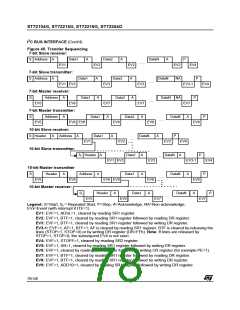
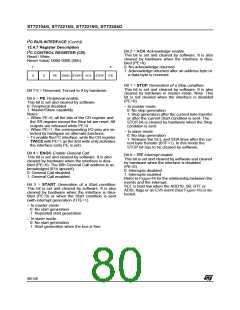
Figure 46. Event Flags and Interrupt Generation
ADD10
ITE
BTF
ADSL
SB
INTERRUPT
EVF
AF
STOPF
ARLO
BERR
*
* EVF can also be set by EV6 or an error from the SR2 register.
Enable
Control from
Bit
Exit
Exit
from
Halt
Event
Flag
Interrupt Event
Wait
Yes
Yes
Yes
Yes
Yes
Yes
Yes
Yes
10-bit Address Sent Event (Master mode)
End of Byte Transfer Event
ADD10
BTF
No
No
No
No
No
No
No
No
Address Matched Event (Slave mode)
Start Bit Generation Event (Master mode)
Acknowledge Failure Event
ADSEL
SB
ITE
AF
Stop Detection Event (Slave mode)
Arbitration Lost Event (Multimaster configuration)
Bus Error Event
STOPF
ARLO
BERR
2
Note: The I C interrupt events are connected to
the same interrupt vector (see Interrupts chapter).
They generate an interrupt if the corresponding
Enable Control Bit is set and the I-bit in the CC reg-
ister is reset (RIM instruction).
79/140

 ETC [ ETC ]