ST6200C/ST6201C/ST6203C
8-BIT TIMER (Cont’d)
9.2.7 Register Description
ETI=0 the timer interrupt is disabled. If ETI=1 and
TMZ=1 an interrupt request is generated.
0: Interrupt disabled (reset state)
1: Interrupt enabled
PRESCALER COUNTER REGISTER (PSCR)
Address: 0D2h - Read/Write
Reset Value: 0111 1111 (7Fh)
7
0
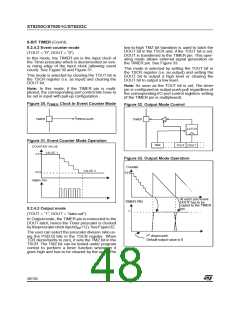
Bit 5 = TOUT Timer Output Control.
When low, this bit selects the input mode for the
TIMER pin. When high the output mode is select-
ed.
PSCR PSCR PSCR PSCR PSCR PSCR PSCR PSCR
0
7
6
5
4
3
2
1
0: Input mode (reset state)
Bit 7 = PSCR7: Not used, always read as “0”.
Bit 6:0 = PSCR[6:0] Prescaler LSB.
1: Output mode, the TIMER pin is configured as
push-pull output
TIMER COUNTER REGISTER (TCR)
Address: 0D3h - Read / Write
Bit 4= DOUT Data Output.
Data sent to the timer output when TMZ is set high
(output mode only). Input mode selection (input
mode only).
Reset Value: 1111 1111 (FFh)
7
0
Bit 3 = PSI: Prescaler Initialize bit.
TCR7 TCR6 TCR5 TCR4 TCR3 TCR2 TCR1 TCR0
Used to initialize the prescaler and inhibit its count-
ing. When PSI=“0” the prescaler is set to 7Fh and
the counter is inhibited. When PSI=“1” the prescal-
er is enabled to count downwards. As long as
PSE=“1” both counter and prescaler are not run-
ning
Bit 7:0 = TCR[7:0] Timer counter bits.
TIMER STATUS CONTROL REGISTER (TSCR)
Address: 0D4h - Read/Write
Reset Value: 0000 0000 (00h)
0: Counting disabled (reset state)
1: Counting enabled
7
0
Bit 1:0 = PS[2:0] Prescaler Mux. Select.
These bits select the division ratio of the prescaler
register.
TMZ
ETI
TOUT DOUT PSI
PS2
PS1
PS0
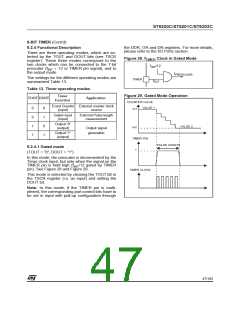
Bit 7 = TMZ Timer Zero bit.
Table 14. Prescaler Division Factors
A low-to-high transition indicates that the timer
count register has underflowed. It means that the
TCR value has changed from 00h to FFh.
This bit must be cleared by user software.
0: Counter has not underflowed
PS2
0
PS1
0
PS0
0
Divided by
1
2
4
0
0
1
0
1
0
1: Counter underflow occurred
0
1
1
8
1
1
1
1
0
0
1
1
0
1
0
1
16
32
64
128
Bit 6 = ETI Enable Timer Interrupt.
When set, enables the timer interrupt request. If
Table 15. 8-Bit Timer Register Map and Reset Values
Address
Register Label
7
6
5
4
3
2
1
0
(Hex.)
PSCR
Reset Value
PSCR7 PSCR6 PSCR5 PSCR4 PSCR3 PSCR2 PSCR1 PSCR0
0D2h
0
1
1
1
1
1
1
1
TCR
Reset Value
TCR7
1
TCR6
1
TCR5
1
TCR4
1
TCR3
1
TCR2
1
TCR1
1
TCR0
1
0D3h
0D4h
TSCR
Reset Value
TMZ
0
ETI
0
TOUT
0
DOUT
0
PSI
0
PS2
0
PS1
0
PS0
0
50/104
1

 ETC [ ETC ]