ST6200C/ST6201C/ST6203C
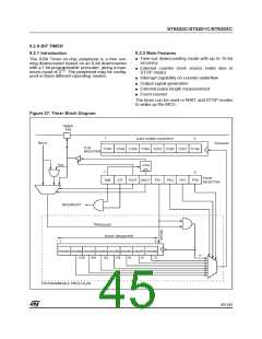
8-BIT TIMER (Cont’d)
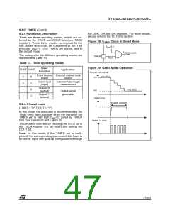
9.2.4.2 Event counter mode
(TOUT = “0”, DOUT = “0”)
low-to-high TMZ bit transition is used to latch the
DOUT bit in the TSCR and, if the TOUT bit is set,
DOUT is transferred to the TIMER pin. This oper-
ating mode allows external signal generation on
the TIMER pin. See Figure 33.
In this mode, the TIMER pin is the input clock of
the Timer prescaler which is decremented on eve-
ry rising edge of the input clock (allowing event
count). See Figure 30 and Figure 31.
This mode is selected by setting the TOUT bit in
the TSCR register (i.e. as output) and setting the
DOUT bit to output a high level or clearing the
DOUT bit to output a low level.
This mode is selected by clearing the TOUT bit in
the TSCR register (i.e. as input) and clearing the
DOUT bit.
Note: As soon as the TOUT bit is set, The timer
pin is configured as output push-pull regardless of
the corresponding I/O port control registers setting
(if the TIMER pin is multiplexed).
Note: In this mode, if the TIMER pin is multi-
plexed, the corresponding port control bits have to
be set in input with pull-up configuration.
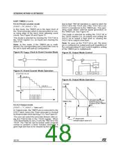
Figure 30. f
Clock in Event Counter Mode
TIMER
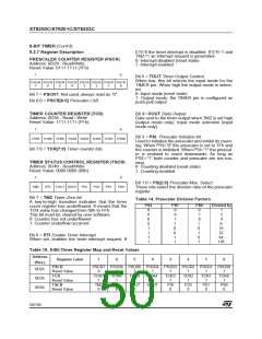
Figure 32. Output Mode Control
f
TIMER
PRESCALER
TIMER
LATCH
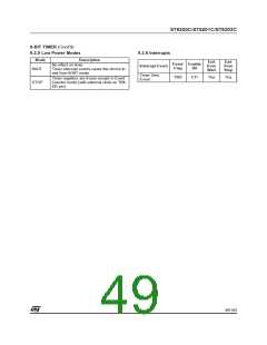
Figure 31. Event Counter Mode Operation
TMZ
TOUT DOUT
COUNTER VALUE
VALUE 1
XX1
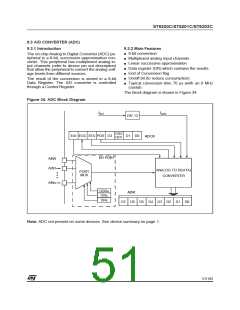
Figure 33. Output Mode Operation
Counter
FFh
VALUE 2
XX2
TIMER PIN
At each zero event
TIMER PIN
1
DOUT has to be
copied to the TIMER
pin
9.2.4.3 Output mode
(TOUT = “1”, DOUT = “data out”)
In Output mode, the TIMER pin is connected to the
DOUT latch, hence the Timer prescaler is clocked
by theprescalerclock input(f /12). SeeFigure32.
INT
The user can select the prescaler division ratio us-
ing the PS[2:0] bits in the TSCR register. When
TCR decrements to zero, it sets the TMZ bit in the
TSCR. The TMZ bit can be tested under program
control to perform a timer function whenever it
goes high and has to be cleared by the user. The
1
st downcount:
Default output value is 0
48/104
1

 ETC [ ETC ]