ST6200C/ST6201C/ST6203C
8-BIT TIMER (Cont’d)
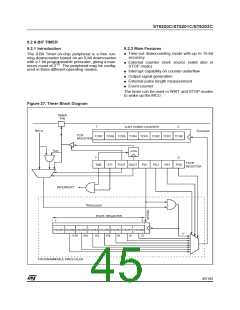
9.2.4 Functional Description
the DDR, OR and DR registers. For more details,
please refer to the I/O Ports section.
There are three operating modes, which are se-
lected by the TOUT and DOUT bits (see TSCR
register). These three modes correspond to the
two clocks which can be connected to the 7-bit
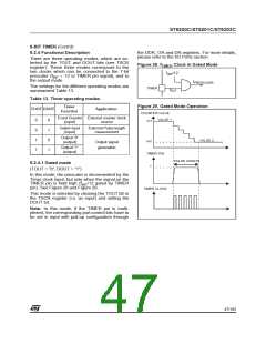
Figure 28. f
Clock in Gated Mode
TIMER
f
/12
INT
prescaler (f
the output mode.
÷ 12 or TIMER pin signal), and to
INT
f
PRESCALER
The settings for the different operating modes are
summarized Table 13.
TIMER
f
EXT
Table 13. Timer operating modes
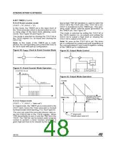
Figure 29. Gated Mode Operation
Timer
Function
TOUT DOUT
Application
COUNTER VALUE
Event Counter External counter clock
VALUE 1
xx1
0
0
1
1
0
1
0
1
(input)
source
Gated input
(input)
External Pulse length
measurement
Output “0”
(output)
VALUE 2
xx2
Output signal
generation
Output “1”
(output)
TIMER PIN
1
PULSE LENGTH
9.2.4.1 Gated mode
(TOUT = “0”, DOUT = “1”)
In this mode, the prescaler is decremented by the
Timer clock input, but only when the signal on the
TIMER pin is held high (f /12 gated by TIMER
INT
pin). See Figure 28 and Figure 29.
TIMER CLOCK
This mode is selected by clearing the TOUT bit in
the TSCR register (i.e. as input) and setting the
DOUT bit.
Note: In this mode, if the TIMER pin is multi-
plexed, the corresponding port control bits have to
be set in input with pull-up configuration through
47/104
1

 ETC [ ETC ]