ST6200C/ST6201C/ST6203C
6 INTERRUPTS
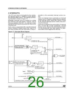
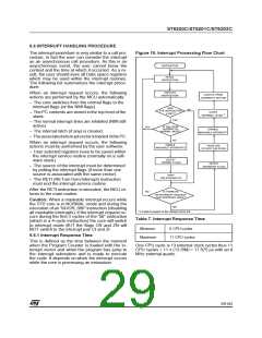
The ST6 core may be interrupted by four maska-
ble interrupt sources, in addition to a Non Maska-
ble Interrupt (NMI) source. The interrupt process-
ing flowchart is shown in Figure 18.
struction to the associated interrupt service rou-
tine.
When an interrupt source generates an interrupt
request, the PC register is loaded with the address
of the interrupt vector, which then causes a Jump
to the relevant interrupt service routine, thus serv-
icing the interrupt.
Maskable interrupts must be enabled by setting
the GEN bit in the IOR register. However, even if
they are disabled (GEN bit = 0), interrupt events
are latched and may be processed as soon as the
GEN bit is set.
Interrupt are triggered by events either on external
pins, or from the on-chip peripherals. Several
events can be ORed on the same interrupt vector.
On-chip peripherals have flag registers to deter-
mine which event triggered the interrupt.
Each source is associated with a specific Interrupt
Vector, located in Program space (see Table 8). In
the vector location, the user must write a Jump in-
Figure 17. Interrupts Block Diagram
V
DD
VECTOR #0
NMI
LATCH
CLEARED BY H/W
AT START OF VECTOR #0 ROUTINE
I/O PORT REGISTER
PA1..PA3
“INPUT WITH INTERRUPT”
CONFIGURATION
LATCH
0
VECTOR #1
CLEARED BY H/W
AT START OF
1
VECTOR #1 ROUTINE
LES BIT
(IOR REGISTER)
EXIT FROM
STOP/WAI T
PB0..PB1
PB3
PB5..PB7
I/O PORT REGISTER
“INPUT WITH INTERRUPT”
CONFIGURATION
VECTOR #2
LATCH
ESB BIT
CLEARED
(IOR REGISTER)
BY H/W AT START OF
VECTOR #2 ROUTINE
TMZ BIT
ETI BIT
VECTOR #3
VECTOR #4
TIMER
(TSCR REGISTER)
EAI BIT
EOC BIT
A/D CONVERTER *
(ADCR REGISTER)
GEN BIT
(IOR REGISTER)
* Depending on device. See device summary on page 1.
26/104
1

 ETC [ ETC ]