ST6200C/ST6201C/ST6203C
6.7 REGISTER DESCRIPTION
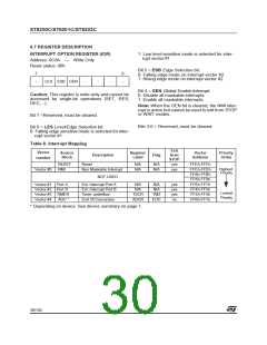
INTERRUPT OPTION REGISTER (IOR)
1: Low level sensitive mode is selected for inter-
rupt vector #1
Address: 0C8h
—
Write Only
Reset status: 00h
Bit 5 = ESB Edge Selection bit.
0: Falling edge mode on interrupt vector #2
1: Rising edge mode on interrupt vector #2
7
-
0
-
LES ESB GEN
-
-
-
Bit 4 = GEN Global Enable Interrupt.
0: Disable all maskable interrupts
1: Enable all maskable interrupts
Caution: This register is write-only and cannot be
accessed by single-bit operations (SET, RES,
DEC,...).
Note: When the GEN bit is cleared, the NMI inter-
rupt is active but cannot be used to exit from STOP
or WAIT modes.
Bit 7 =Reserved, must be cleared.
Bits 3:0 = Reserved, must be cleared.
Bit 6 = LES Level/Edge Selection bit.
0: Falling edge sensitive mode is selected for inter-
rupt vector #1
Table 8. Interrupt Mapping
Exit
from
STOP
Vector
Source
Block
Register
Label
Vector
Address
Priority
Order
Description
Flag
number
RESET
NMI
Reset
N/A
N/A
N/A
N/A
yes
yes
FFEh-FFFh
FFCh-FFDh
FFAh-FFBh
FF8h-FF9h
FF6h-FF7h
FF4h-FF5h
FF2h-FF3h
FF0h-FF1h
Highest
Priority
Vector #0
Non Maskable Interrupt
NOT USED
Vector #1 Port A
Vector #2 Port B
Vector #3 TIMER
Ext. Interrupt Port A
Ext. Interrupt Port B
Timer underflow
N/A
N/A
N/A
N/A
yes
yes
yes
no
Lowest
Priority
TSCR
ADCR
TMZ
EOC
Vector #4
ADC *
End Of Conversion
* Depending on device. See device summary on page 1.
30/104
1

 ETC [ ETC ]