ST6200C/ST6201C/ST6203C
5.2 LOW VOLTAGE DETECTOR (LVD)
The on-chip Low Voltage Detector is enabled by
setting a bit in the option bytes (refer to the Option
Bytes section of this document).
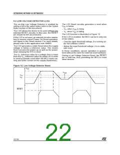
The LVD Reset circuitry generates a reset when
is below:
V
DD
– VIT+ when V is rising
DD
The LVD allows the device to be used without any
external RESET circuitry. In this case, the RESET
pin should be left unconnected.
– VIT- when V is falling
DD
The LVD function is illustrated in Figure 12.
If the LVD is enabled, the MCU can be in only one
of two states:
If the LVD is not used, an external circuit is manda-
tory to ensure correct Power On Reset operation,
see figure in the Reset section. For more details,
please refer to the application note AN669.
– Over the input threshold voltage, it is running un-
der full software control
The LVD generates a static Reset when the supply
voltage is below a reference value. This means
that it secures the power-up as well as the power-
down keeping the ST6 in reset.
– Below the input threshold voltage, it is in static
safe reset
In these conditions, secure operation is guaran-
teed without the need for external reset hardware.
The VIT- reference value for a voltage drop is lower
than the VIT+ reference value for power-on in order
to avoid a parasitic reset when the MCU starts run-
ning and sinks current on the supply (hysteresis).
During a Low Voltage Detector Reset, the RESET
pin is held low, thus permitting the MCU to reset
other devices.
Figure 12. Low Voltage Detector Reset
V
DD
V
hyst
V
V
IT+
IT-
RESET
22/104
1

 ETC [ ETC ]