ST6200C/ST6201C/ST6203C
6.5 EXTERNAL INTERRUPTS (I/O Ports)
External interrupt vectors can be loaded into the
PC register if the corresponding external interrupt
occurred and if the GEN bit is set. These interrupts
allow the processor to exit from STOP mode.
This is due to the vector #2 circuitry.The worka-
round is to discard this first interrupt request in the
routine (using a flag for example).
Masking of One Interrupt by Another on Vector
#2.
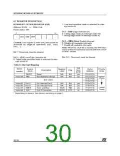
The external interrupt polarity is selected through
the IOR register.
When two or more port pins (associated with inter-
rupt vector #2) are configured together as input
with interrupt (falling edge sensitive), as long as
one pin is stuck at ’0’, the other pin can never gen-
erate an interrupt even if an active edge occurs at
this pin. The same thing occurs when one pin is
stuck at ’1’ and interrupt vector #2 is configured as
rising edge sensitive.
External interrupts are linked to vectors #1 and #
2.
Interrupt requests on vector #1 can be configured
either as edge or level-sensitive using the LES bit
in the IOR Register.
Interrupt requests from vector #2 are always edge
sensitive. The edge polarity can be configured us-
ing the ESB bit in the IOR Register.
To avoid this the first pin must input a signal that
goes back up to ’1’ right after the falling edge. Oth-
erwise, in the interrupt routine for the first pin, de-
activate the “input with interrupt” mode using the
port control registers (DDR, OR, DR). An active
edge on another pin can then be latched.
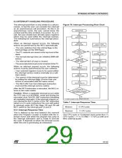
In edge-sensitive mode, a latch is set when a edge
occurs on the interrupt source line and is cleared
when the associated interrupt routine is started.
So, an interrupt request can be stored until com-
pletion of the currently executing interrupt routine,
before being processed. If several interrupt re-
quests occurs before completion of the current in-
terrupt routine, only the first request is stored.
I/O port Configuration Spurious Interrupt on
Vector #2
If a pin associated with interrupt vector #2 is in ‘in-
put with pull-up’ state, a ‘0’ level is present on the
pin and the ESB bit = 0, when the I/O pin is config-
ured as interrupt with pull-up by writing to the
DDRx, ORx and DRx register bits, an interrupt is
latched although a falling edge may not have oc-
curred on the associated pin.
Storing of interrupt requests is not possible in level
sensitive mode. To be taken into account, the low
level must be present on the interrupt pin when the
MCU samples the line after instruction execution.
6.5.1 Notes on using External Interrupts
ESB bit Spurious Interrupt on Vector #2
In the opposite case, if the pin is in interrupt with
pull-up state , a 0 level is present on the pin and
the ESB bit =1, when the I/O port is configured as
input with pull-up by writing to the DDRx, ORx and
DRx bits, an interrupt is latched although a rising
edge may not have occurred on the associated
pin.
If a pin associated with interrupt vector #2 is con-
figured as interrupt with pull-up, whenever vector
#2 is configured to be rising edge sensitive (by set-
ting the ESB bit in the IOR register), an interrupt is
latched although a rising edge may not have oc-
cured on the associated pin.
28/104
1

 ETC [ ETC ]