PIC12F510/16F506
10.3 Reset
The device differentiates between various kinds of
Reset:
• Power-on Reset (POR)
• MCLR Reset during normal operation
• MCLR Reset during Sleep
• WDT Time-out Reset during normal operation
• WDT Time-out Reset during Sleep
• Wake-up from Sleep Reset on pin change
• Wake-up from Sleep Reset on comparator
change
Some registers are not reset in any way, they are
unknown on POR and unchanged in any other Reset.
Most other registers are reset to “Reset state” on
Power-on Reset (POR), MCLR, WDT or Wake-up from
Sleep Reset on pin change or wake-up from Sleep
Reset on comparator change. The exceptions are TO,
PD, CWUF and RBWUF/GPWUF bits. They are set or
cleared differently in different Reset situations. These
bits are used in software to determine the nature of
Reset. See Table 10-4 for a full description of Reset
states of all registers.
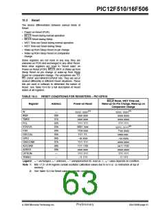
TABLE 10-3: RESET CONDITIONS FOR REGISTERS – PIC12F510
MCLR Reset, WDT Time-out,
Register
Address
Power-on Reset
Wake-up On Pin Change, Wake-up on
Comparator Change
W
—
qqqq qqqu(1)
xxxx xxxx
xxxx xxxx
1111 1111
0001 1xxx
110x xxxx
1111 111-
--xx xxxx
qqqq qqqu(1)
uuuu uuuu
uuuu uuuu
1111 1111
qq0q quuu(2)
11uu uuuu
uuuu uuu-
--uu uuuu
INDF
00h
01h
02h
03h
04h
05h
06h
07h
08h
09h
—
TMR0
PCL
STATUS
FSR
OSCCAL
GPIO
CM1CON0
ADCON0
ADRES
OPTION
TRISIO
1111 1111
1111 1100
xxxx xxxx
1111 1111
--11 1111
uuuu uuuu
uu11 1100
uuuu uuuu
1111 1111
—
--11 1111
Legend: u= unchanged, x= unknown, – = unimplemented bit, read as ‘0’, q= value depends on condition.
Note 1: Bits <7:2> of W register contain oscillator calibration values due to MOVLW XXinstruction at top of
memory.
2: See Table 10-5 for Reset value for specific conditions.
© 2006 Microchip Technology Inc.
Preliminary
DS41268B-page 61

 ETC [ ETC ]