PIC12F510/16F506
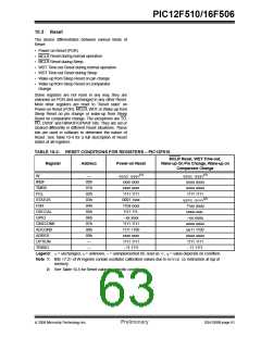
Although the oscillator will operate with no external
capacitor (CEXT = 0pF), we recommend using values
above 20 pF for noise and stability reasons. With no
capacitance or small external capacitance, the oscilla-
tion frequency can vary dramatically due to changes in
external capacitances, such as PCB trace capacitance
or package lead frame capacitance.
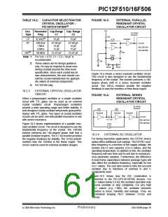
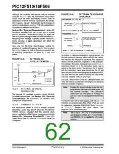
FIGURE 10-6:
EXTERNAL CLOCK INPUT
OPERATION
PIC16F506: EC, HS, XT, LP
Clock From
ext. system
RB5/OSC1/CLKIN
(1)
Section 13.0 “Electrical Characteristics”, shows RC
frequency variation from part-to-part due to normal
process variation. The variation is larger for larger val-
ues of R (since leakage current variation will affect RC
frequency more for large R) and for smaller values of C
(since variation of input capacitance will affect RC
frequency more).
OSC2/CLKOUT/RB4
OSC2/CLKOUT/RB4
PIC12F510: XT, LP
Clock From
ext. system
GP5/OSC1/CLKIN
GP4/OSC2
OSC2
Also, see the Electrical Specifications section for
variation of oscillator frequency due to VDD for given
REXT/CEXT values, as well as frequency variation due
to operating temperature for given R, C and VDD
values.
Note 1: RB4 is available in EC mode only.
In addition, a calibration instruction is programmed into
the last address of memory, which contains the calibra-
tion value for the internal RC oscillator. This location is
always uncode protected, regardless of the code-pro-
tect settings. This value is programmed as a MOVLW XX
instruction where XX is the calibration value, and is
placed at the Reset vector. This will load the W register
with the calibration value upon Reset and the PC will
then roll over to the users program at address 0x000.
The user then has the option of writing the value to the
OSCCAL Register (05h) or ignoring it.
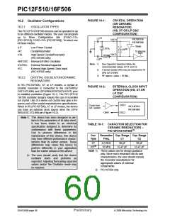
FIGURE 10-5:
EXTERNAL RC
OSCILLATOR MODE
VDD
REXT
Internal
clock
OSC1
N
CEXT
VSS
PIC12F510
PIC16F506
OSCCAL, when written to with the calibration value, will
“trim” the internal oscillator to remove process variation
from the oscillator frequency.
OSC2/CLKOUT
FOSC/4
Note:
Erasing the device will also erase the pre-
programmed internal calibration value for
the internal oscillator. The calibration
value must be read prior to erasing the
part so it can be reprogrammed correctly
later.
10.2.5
INTERNAL 4/8 MHz RC
OSCILLATOR
The internal RC oscillator provides a fixed 4/8 MHz
(nominal) system clock (see Section 13.0 “Electrical
Characteristics” for information on variation over
voltage and temperature).
For the PIC12F510/16F506 devices, only bits <7:1> of
OSCCAL are implemented. Bits CAL6-CAL0 are used
for calibration. Adjusting CAL6-CAL0 from ‘0000000’
to ‘1111111’ changes the clock speed. See
Register 4-3 for more information.
10.2.6
EXTERNAL CLOCK IN
For applications where a clock is already available
elsewhere, users may directly drive the PIC12F510/
16F506 devices provided that this external clock
source meets the AC/DC timing requirements listed in
Section 10.6 “Watchdog Timer (WDT)”. Figure 10-6
below shows how an external clock circuit should be
configured.
Note:
The 0 bit of OSCCAL is unimplemented
and should be written as ‘0’ when modify-
ing OSCCAL for compatibility with future
devices.
DS41268B-page 60
Preliminary
© 2006 Microchip Technology Inc.

 ETC [ ETC ]